LG KE990 Service Manual
LG KE990 - LG Viewty Cell Phone 100 MB Manual
 |
View all LG KE990 manuals
Add to My Manuals
Save this manual to your list of manuals |
LG KE990 manual content summary:
- LG KE990 | Service Manual - Page 1
Service Manual Internal Use Only Service Manual KE990/KE990c Date: April, 2008 / Issue 1.0 Model : KE990/KE990c - LG KE990 | Service Manual - Page 2
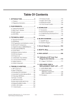
102 4.10 Micro SD trouble 104 4.11 Audio trouble 105 4.12 Camera trouble 118 4.13 Main LCD trouble 121 4.14 Bluetooth trouble 124 4.15 Touch Screen trouble 126 5. DOWNLOAD 127 5.1 Introduction 127 5.2 Downloading Procedure 127 5.3 Troubleshooting Download Errors .......142 5.4 Caution 147 - LG KE990 | Service Manual - Page 3
LGE Internal Use Only -4- Copyright © 2008 LG Electronics. Inc. All right reserved. Only for training and service purposes - LG KE990 | Service Manual - Page 4
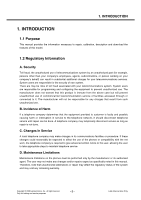
's behalf) can result in substantial additional charges for your telecommunications services. System users are responsible for the security of own system. There are may be risks of toll fraud associated with your telecommunications system. System users are responsible for programming and configuring - LG KE990 | Service Manual - Page 5
provide information such as the following to the end user. F. Pictures The pictures in this manual are for illustrative purposes only; your actual hardware may look slightly different. G. Interference and Attenuation A phone may interfere with sensitive laboratory equipment, medical equipment, etc - LG KE990 | Service Manual - Page 6
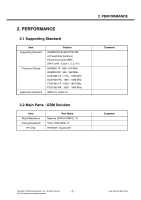
2. PERFORMANCE 2.1 Supporting Standard Item Supporting Standard Frequency Range Application Standard Feature GSM900/DCS1800/PCS1900 with seamless 1930 - 1990 MHz WAP 2.0, JAVA 2.0 2.2 Main Parts : GSM Solution Item Digital Baseband Analog Baseband RF Chip Part Name Neptune (D761811BZVL): TI - LG KE990 | Service Manual - Page 7
None Comment With Battery @ Paging Period 9 @ Power Off / 800mAh @ GSM850 / 800mAh Class4 (GSM900) Class1 (PCS) Class1 (DCS) E2 (GSM900) E2 (PCS) E2 (DCS) One button access LGE Internal Use Only -8- Copyright © 2008 LG Electronics. Inc. All right reserved. Only for training and service purposes - LG KE990 | Service Manual - Page 8
Item Keypad ANT System connector Ear Phone Jack PC synchronization Memory Speech coding Data & Fax Vibrator Blue Tooth MIDI(for Buzzer Function) Music Player Video Player Camcorder Voice Recording Speaker Phone mode Support Travel Adapter CDROM Stereo Headset Data Cable T-Flash (External Memory - LG KE990 | Service Manual - Page 9
2. PERFORMANCE 2.4 HW SPEC. Item Description 1 Frequency Band 2 Phase Error 3 Frequency Error 11 21 dBm 3dB 19 5 dBm 5dB 12 19 dBm 3dB DCS / PCS Level Power Toler. Level Power Toler. 0 30 dBm 2dB 8 14 © 2008 LG Electronics. Inc. All right reserved. Only for training and service purposes - LG KE990 | Service Manual - Page 10
1,200 ~ 1,800 1,800 ~ 3,000 3,000 ~ 6,000 6,000 DCS / PCS Offset from Carrier (kHz). 100 200 250 400 600 ~ 1,200 1,200 ~ Offset from Carrier (kHz) 400 600 1,200 1,800 Copyright © 2008 LG Electronics. Inc. All right reserved. Only for training and service purposes - 11 - Max. dBc +0.5 -30 -33 -60 - LG KE990 | Service Manual - Page 11
Report accuracy 10 SLR 11 Sending Response 12 RLR 13 Receiving Response Specification DCS / PCS Offset from Carrier (kHz). 400 600 1,200 1,800 Conduction, Emission Status GSM, EGSM Use Only - 12 - Copyright © 2008 LG Electronics. Inc. All right reserved. Only for training and service purposes - LG KE990 | Service Manual - Page 12
800mA):390 Min Under conditions, at least 200 hours: Brand new and full 800mAh battery Full charge, no receive/send and keep GSM in idle mode. Broadcast set off. Signal strength display labove. Backlight of phone set off. At least 80 dB under below conditions: 1. Ringer set as ringer. 2. Test - LG KE990 | Service Manual - Page 13
Voltage = 3.7 V Battery full charge voltage = 4.2 V Capacity: Min 930mAh Switching-mode charger Input: 100 ~ 240 V, 50/60Hz Out put: 5.1V, 700mA Voltage 3.65V ~ 3.35V 3.71V ~ 3.66V 3.78V ~ 3.72V 3.91V ~ 3.79V 4.20V ~ 3.92V LGE Internal Use Only - 14 - Copyright © 2008 LG Electronics. Inc. All - LG KE990 | Service Manual - Page 14
Description The KE990/KE990c supports EGSM-900, DCS-1800, and PCS-1900 based VCO Phone VCTCXO PM6635-3P Input Power Management Voltage R egulat ors General H ous ek eeping User Interfaces IC Copyright © 2008 LG Electronics. Inc. All right reserved. Only for training and service purposes - 15 - LG KE990 | Service Manual - Page 15
charging status, and current flow, as well as user-defined off-chip variables such as temperature, RF output power, and battery ID. Various oscillator, clock, and counter circuits support Only - 16 - Copyright © 2008 LG Electronics. Inc. All right reserved. Only for training and service purposes - LG KE990 | Service Manual - Page 16
PCS-1900). The antenna switch module allows multiple operating bands and modes to share the same antenna. In KE990 all the way into the Software - please see applicable AMSS Software documentation for details. Copyright © 2008 LG Electronics. Inc. All right reserved. Only for training and service - LG KE990 | Service Manual - Page 17
filter outputs are buffered and passed on to the ESM6270 IC for further processing LGE Internal Use Only [Fig 3.2.2] RTR6235 RX feature - 18 - Copyright © 2008 LG Electronics. Inc. All right reserved. Only for training and service purposes - LG KE990 | Service Manual - Page 18
The RTR6235 IC is able to support GSM 850/900 and GSM 1800/1900 mode transmitting. This design guideline shows a Quad-band GSM application. Both high-band and low band band Copyright © 2008 LG Electronics. Inc. All right reserved. Only for training and service purposes - 19 - LGE Internal Use Only - LG KE990 | Service Manual - Page 19
integrated LO generation and distribution circuits are driven by internal VCOs to support various modes to yield highly flexible quadrature LO outputs that drive all GSM LGE Internal Use Only - 20 - Copyright © 2008 LG Electronics. Inc. All right reserved. Only for training and service purposes - LG KE990 | Service Manual - Page 20
equipment uses a single antenna to support all handset operating modes, with an antenna switch module select the operating frequency and band. The active connection control logic Copyright © 2008 LG Electronics. Inc. All right reserved. Only for training and service purposes - 21 - LGE Internal Use - LG KE990 | Service Manual - Page 21
- Supports coin cell backup battery (including charging) - Battery voltage detectors with programmable thresholds - VDD collapse protection - Charger current regulation and real-time monitoring for over-current protection - Charger transistor protection by power limit control - Control drivers for - LG KE990 | Service Manual - Page 22
as keypad backlight, LCD backlight, camera flash, and general-purpose drivers - Vibration motor driver programmable from 1.2 to 3.1V in 100 mV increments - Speaker driver with programmable gain, turn-on time, and muting; differential operation (drives external 8 Ω speakers with volume controlled - LG KE990 | Service Manual - Page 23
3. TECHNICAL BRIEF LGE Internal Use Only [Figure 3.4.3] PM6635 Block Diagram - 24 - Copyright © 2008 LG Electronics. Inc. All right reserved. Only for training and service purposes - LG KE990 | Service Manual - Page 24
applications. This module has been optimized for excellent EDGE efficiency and Pout in a Polar Loop environment at EDGE class E2+ operation operations, and serves as the AM/AM path in EDGE operations. GSM_PA_BAND MODE LOW HIGH GSM850/900 DCS/PCS [Figure 3.4.4] GSM PAM Schematic R112 100 R111 - LG KE990 | Service Manual - Page 25
and Antenna. Figure3.4.5 shows the bluetooth system architecture in the KE990/KE990c. AN T LB RQ-2B43A Bl P VD D_A 2 3 [Figure 3.4.5] Bluetooth system architecture LGE Internal Use Only - 26 - Copyright © 2008 LG Electronics. Inc. All right reserved. Only for training and service purposes - LG KE990 | Service Manual - Page 26
with RDS/RBDS demodulator and decoder for low voltage applications, with fully integrated IF selectivity and demodulation. This equipment tunes the European, US, and Japanese FM bands. Figure3.4.6 shows the FM Radio system architecture in the KE990. From MMI FM_AN T RFIN1 RFIN2 FM Radio TEA5766 UK - LG KE990 | Service Manual - Page 27
on par with portable music players ■ Vocoder support (AMR, FR, EFR, HR) ■ Advanced 14 x 14 mm, 0.5 mm pitch, 409-pin lead-free CSP technology ■ SD/SDIO hardware support LGE Internal Use Only - 28 - Copyright © 2008 LG Electronics. Inc. All right reserved. Only for training and service purposes - LG KE990 | Service Manual - Page 28
VREG_ MSMA_ 2.6V USIM_ DATA/CLK/RST_N SSBDT_ PM RESET _IN_ N PS_ HOLD PM_INT _ N SLEEP_ CLK USB_OE_EN _ CTRL VPWR WLED[1: 5] WLED_ PWR Charge Pump AAT 3169 IFO VPWR MMC_ SELECT_N From LG Electronics. Inc. All right reserved. Only for training and service purposes - 29 - LGE Internal Use Only - LG KE990 | Service Manual - Page 29
_PA _EN GSM _PA _BAND From MSM 6280 ANT _SEL [1:0] From MSM 6280 4BAND GSM RX (850/900 /DCS /PCS -- Balan ce ) 4 DAC _REF [RF Trance ive r ] RTR6275 QCT 8 x 8 x 0.9 PWR _DET Use Only - 30 - Copyright © 2008 LG Electronics. Inc. All right reserved. Only for training and service purposes - LG KE990 | Service Manual - Page 30
ARM926EJ-S microprocessor. This microprocessor, through the system software, controls most of the functionality for the ESM fax ❏ No sub-rates are supported. 3.6.3 GPRS features ■ Packet switched data (GPRS) ❏ DTM (Simple Class A) operation ❏ Multi-slot class 12 data services ❏ CS schemes: CS1, CS2 - LG KE990 | Service Manual - Page 31
buses separating the high-speed memory subsystem (EBI1) from low-speed ❏ peripherals (EBI2) such as LCD panels ❏ 1.8 V or 2.6 V memory interface support (excluding EBI1) LGE Internal Use Only - 32 - Copyright © 2008 LG Electronics. Inc. All right reserved. Only for training and service purposes - LG KE990 | Service Manual - Page 32
game performance ❏ Integrated Java and 2D/3D graphics accelerator with Sprite engine ■ Enable various accessories via USB host connectivity. ❏ Integrated USB host controller functionality ■ Enable compelling visual and audio applications. Qcamera ■ High-quality digital camera processing, supporting - LG KE990 | Service Manual - Page 33
services: Qvideophone ■ A two-way mobile video conferencing solution that delivers 15 fps @ QCIF ■ Video Codecs supported: MPEG-4 and H.263 ■ Audio Codecs supported: AMR-NB. Qcamcorder ■ Real time mobile video encoder ■ Video Codecs supported bend range support ■ LED/vibrate support ■ Scalable - LG KE990 | Service Manual - Page 34
can be configured for different operating modes and for minimum power consumption, extending battery life in Standby mode. The SSBI also controls DC baseband offset errors. Copyright © 2008 LG Electronics. Inc. All right reserved. Only for training and service purposes - 35 - LGE Internal Use - LG KE990 | Service Manual - Page 35
integrated ARM9TDMI processor downloads the firmware into the QDSP4000 and configures QDSP4000 to support the desired functionality. 3.6.12 ARM Microprocessor subsystem The ESM6270 device uses an embedded ARM926EJ-S microprocessor. This microprocessor, through the system software, controls most of - LG KE990 | Service Manual - Page 36
the GPIO pins have alternate functions supported on them. The alternate functions of these pins is documented in the various software releases. 3.6.15 UART The ESM6270 device employs universal serial bus (USB) controller that supports both unidirectional and bidirectional transceiver interfaces. The - LG KE990 | Service Manual - Page 37
power supply AAT3169 : LCD Backlight/Flash charge pump 3.7.2 PM6635 The PM6635 device (Figure 3.7) integrates all wireless handset power management. The power management portion accepts power from all the most common sources - battery, external charger, adapter, coin cell back-up - and generates all - LG KE990 | Service Manual - Page 38
3. TECHNICAL BRIEF Figure 3.7. PM6635 Functional Block Diagram Copyright © 2008 LG Electronics. Inc. All right reserved. Only for training and service purposes - 39 - LGE Internal Use Only - LG KE990 | Service Manual - Page 39
block in PM6635 is used for battery charging. It is possible to set limits for the charging current. The external supply typically 69~45 (%) 3.70V~3.62V 44~20 (%) 3.61V~3.50V 19~3 (%) KE990 Battery Bar Display(Stand By Condition) 3.49V~3.28V 2~0 (%) LGE Internal Use Only - 40 - LG KE990 | Service Manual - Page 40
-ion and nickel-based batteries, with its performance specified below (3.2V). The charging current is set to 80mA. Parameter Min Typ Max Unit Trickle Current 60 80 100 mA PM6635 Copyright © 2008 LG Electronics. Inc. All right reserved. Only for training and service purposes - 41 - LGE - LG KE990 | Service Manual - Page 41
The PM6635 IC supports constant current charging of the main battery by controlling the charger pass transistor and the battery transistor. The constant current charging continues until the battery reaches its target voltage, 4.2V. Constant Voltage Charging Constant voltage charging begins when the - LG KE990 | Service Manual - Page 42
high speed synchronous memory devices. EBI2 was targeted towards supporting slower asynchronous devices such as LCD, NAND flash, SRAM, etc. In addition, ESM6270 provide SD bus interface. KE990 supports 512MByte free user memory using SD interface. • EBI1 Features - 16 bit static and dynamic - LG KE990 | Service Manual - Page 43
* NAND_RE* NAND_WE* NAND_CLE NAND_WP* NAND_ALE NAND_READY DATA[15:0] NAND 2Gb (256MB) Figure. Simplified Block Diagram of Memory Interface LGE Internal Use Only - 44 - Copyright © 2008 LG Electronics. Inc. All right reserved. Only for training and service purposes - LG KE990 | Service Manual - Page 44
3. TECHNICAL BRIEF 3.9 H/W Sub System 3.9.1 RF Interface A. RTR6235(WCDMA_Tx, GSM_Tx/Rx) ESM6270 controls RF part(RTR6235) using these signals. of RF Interface of ESM6270 Copyright © 2008 LG Electronics. Inc. All right reserved. Only for training and service purposes - 45 - LGE Internal Use Only - LG KE990 | Service Manual - Page 45
.2M) Control • PA_ON : WCDMA(2100) TX Power Amp Enable • ANT_SEL[0-2] : Ant Switch Module Mode Selection(WCDMA,GSM Tx/Rx,DCS-PCS Tx/Rx) • GSM_PA_BAND : GSM/DCS-PCS Band Selection of Power Amp • GSM_PA_RAMP : Power Amp Gain Control of APC_IC • GSM_PA_EN : Power Amp Gain Control Enable of APC_IC LGE - LG KE990 | Service Manual - Page 46
MSM Sub System 3.9.2.1 SIM Interface SIM interface scheme is shown in Figure. And, there control signals are followed • SIM_CLK : SIM Clock • SIM_Reset : SIM Reset • SIM_Data : SIM Data T/Rx 3. TECHNICAL BRIEF ESM6270 SIM CLK SIM Reset SIM Data PM6635 VREG_UIM 2.85V SIM CLK SIM Reset SIM Data - LG KE990 | Service Manual - Page 47
provide an efficient interconnect between the mobile phone and a personal computer (PC). The USB interface of the of operation, namely low-speed (1.5 Mbps) and full-speed (12 Mbps), both of which are supported by the LG Electronics. Inc. All right reserved. Only for training and service purposes - LG KE990 | Service Manual - Page 48
Note RF PAM Temperature Check Battery voltage level ADC Reference voltage Ear jack Detection for TTY PCB Version Check Battery Temperature Check Table. HKADC channel table Copyright © 2008 LG Electronics. Inc. All right reserved. Only for training and service purposes - 49 - LGE Internal Use - LG KE990 | Service Manual - Page 49
[2] KEY_COL[0] KEY_COL[1] R701 51K 700 701 SEND CLR EVLC14S02050 EVLC14S02050 EVLC14S02050 VA701 VA702 VA703 Figure. Main Keypad Circuit LGE Internal Use Only - 50 - Copyright © 2008 LG Electronics. Inc. All right reserved. Only for training and service purposes - LG KE990 | Service Manual - Page 50
[1] KEY_COL[0] KEY_COL[1] 900 SW900 LOCK KEY CAMERA FOCUS Figure. Side Keypad Circuit PM_ON_SW_N END END EVL14K02200 VA700 ON_SW KEY Figure. END Keypad Circuit Copyright © 2008 LG Electronics. Inc. All right reserved. Only for training and service purposes - 51 - LGE Internal Use Only - LG KE990 | Service Manual - Page 51
10p 10p 10p C614 0.1u ICVL0518100Y500FR VA601 ICVL0518100Y500FR VA600 EVLC18S02015 VA602 Figure. Camera PCB Board to Board Connector LGE Internal Use Only - 52 - Copyright © 2008 LG Electronics. Inc. All right reserved. Only for training and service purposes - LG KE990 | Service Manual - Page 52
master clock to camera module, vertical sync signal, horizontal sync signal, reset System Clock Input Ground Voltage Supply(DSP Core) Table. Interface between MEGA Camera Module and MAIN PCB (in camera module) Copyright © 2008 LG Electronics. Inc. All right reserved. Only for training and service - LG KE990 | Service Manual - Page 53
mode(Main LCD) : Normally Black, Transmissive VA mode 265K colors - LCD Driver IC : LS030B3UX01(Magnachip) - Driving Method : A-Si TFT Active Matrix - 16 Block Diagram LGE Internal Use Only - 54 - Copyright © 2008 LG Electronics. Inc. All right reserved. Only for training and service purposes - LG KE990 | Service Manual - Page 54
1 9 INOUT_A1 INOUT_B1 2 8 INOUT_A2 INOUT_B2 3 7 INOUT_A3 INOUT_B3 4 6 INOUT_A4 INOUT_B4 LCD_DATA[12] LCD_DATA[13] LCD_DATA[14] LCD_DATA[15] 5 G1 10 G2 Copyright © 2008 LG Electronics. Inc. All right reserved. Only for training and service purposes - 55 - LGE Internal Use Only - LG KE990 | Service Manual - Page 55
differential microphone inputs, one differential auxiliary input and a two-stage audio amplifier. Figure. Audio Interface Detailed Diagram(ESM6270) LGE Internal Use Only - 56 - Copyright © 2008 LG Electronics. Inc. All right reserved. Only for training and service purposes - LG KE990 | Service Manual - Page 56
LGE Internal Use Only - 57 - Copyright © 2008 LG Electronics. Inc. All right reserved. Only for training and service purposes Figure . Audio part schematics LINE_ON LINE_OP HPH_R HPH_L EAR1ON EAR1OP MICBIAS AUXOUT HPH_VREF LINE_L_IP LINE_L_IN LINE_R_IP LINE_R_IN AUXIN AUXIP MIC2N MIC2P MIC1N - LG KE990 | Service Manual - Page 57
+ 3 GND OUT VCC 1 VIN- 4 5 HOOK_SENSE_N 1M R906 5.1K C905 R907 0.1u Headset Hook Switch Figure . Audio part schematics LGE Internal Use Only - 58 - Copyright © 2008 LG Electronics. Inc. All right reserved. Only for training and service purposes - LG KE990 | Service Manual - Page 58
/ADC, AMP etc. (WM8983) CN500 21 19 1 2 3 4 5 FB504 L504 2.2uH VREG_MSMP_2.7V R528 100K Figure . Audio part schematics FM_ANT EAR_MIC_P TV_OUT MIDI_EAR_L MIDI_EAR_R Copyright © 2008 LG Electronics. Inc. All right reserved. Only for training and service purposes - 59 - LGE Internal Use Only - LG KE990 | Service Manual - Page 59
Voice Call Speaker Phone Speaker MIDI Bell Headset MIDI Bell Speaker MP3 Headset MP3 Table. Audio Mode Audio & Sound Main Component There are 8 main components in KE990. Component 1 Only - 60 - Copyright © 2008 LG Electronics. Inc. All right reserved. Only for training and service purposes - LG KE990 | Service Manual - Page 60
for Mobile XMF for melodies with custom instruments. • Audio stereo recorder player MP3/WMA • ID3 tags display • Spectral bars • Lyrics display • Equalizer • 3D Surround Audio Copyright © 2008 LG Electronics. Inc. All right reserved. Only for training and service purposes - 61 - LGE Internal - LG KE990 | Service Manual - Page 61
• Key exchange support • True RNG (Random Number Generator) 3.10.4 3D Graphics • 3D hardware + software accelerator targeting VGA 30 fps games with PlayStation™-1 enhanced LGE Internal Use Only - 62 - Copyright © 2008 LG Electronics. Inc. All right reserved. Only for training and service purposes - LG KE990 | Service Manual - Page 62
up to X4 in 16 steps 3.10.6 LCD Port • Output resolution - up to VGA • Supports dual-panels (two LCDs) • Bypass from Host port to LCD CPU bus • Up to 18- Color space reduction Copyright © 2008 LG Electronics. Inc. All right reserved. Only for training and service purposes - 63 - LGE Internal Use - LG KE990 | Service Manual - Page 63
• SPI-flash • CE - ATA HDD. • SDIO peripherals 3.10.12 USB • USB 2.0 High speed/full speed • USB On The Go • USB applications: - USB mass storage - PictBridge - Webcam LGE Internal Use Only - 64 - Copyright © 2008 LG Electronics. Inc. All right reserved. Only for training and service purposes - LG KE990 | Service Manual - Page 64
PWM) 3.10.15 Boot • Host boot • Standalone boot 3.10.16 Debug • JTAG for code debug • UART for fast system ramp up 3.10.17 Power • Very low power consumption, smaller than150mW for all intense multimedia applications. • Low power sleep mode 100 µW - Host can control display audio and peripherals via - LG KE990 | Service Manual - Page 65
and playing voice/music • Media Flash (SmartMedia, NANDFlash, MMC or SD) to store media data (two active I/F, e.g. one NAND and one SD) • Connector to TV [ Figure 3.10 ] LGE Internal Use Only - 66 - Copyright © 2008 LG Electronics. Inc. All right reserved. Only for training and service purposes - LG KE990 | Service Manual - Page 66
A13 HD9 B12 HD10 A12 HD11 B11 A11 HD12 C9 HD13 B10 HD14 HD15 L13 NCSN M13 NALE L12 NCLE [ Block Diagram ] [ Schematics ] Copyright © 2008 LG Electronics. Inc. All right reserved. Only for training and service purposes - 67 - LGE Internal Use Only - LG KE990 | Service Manual - Page 67
This is the default mode. 3.11.3 Camera interface ZR3453X connects with the CCD or CMOS Image Sensor (CIS) via its image sensor port. ZR3453X supports several system configurations: • CCD bayer 10,12,14,16 bit (ZR34532 only) • CMOS bayer 10,12,14,16 bit • YCbCr 8 bit • YCbCr 8 bit with pixel valid - LG KE990 | Service Manual - Page 68
ZR3453X LCD port supports mobile LCD panels of upto a composite video signal. This mode is used in a system where ZR3453X is connected gluelessly to a TV screen that requires Copyright © 2008 LG Electronics. Inc. All right reserved. Only for training and service purposes - 69 - [ Schematics - LG KE990 | Service Manual - Page 69
from the ZR3453X on the way is to the speaker. The microphone appears in Figure 3.11 as a master on the bit clock and frame applications including conversation recording . LGE Internal Use Only [ Figure 3.11 ] - 70 - Copyright © 2008 LG Electronics. Inc. All right reserved. Only for training and service - LG KE990 | Service Manual - Page 70
-up and 15-Kilohm pull-down resistors. • Supports 480-Mbps high-speed, 12-Mbps full-speed and - two-way Control - 2-input , 2-output - Bulk, INT or ISO • Suspend, resume, reset and SOF interface Copyright © 2008 LG Electronics. Inc. All right reserved. Only for training and service purposes - 71 - - LG KE990 | Service Manual - Page 71
has a dedicated port for multimedia cards. It can support SD (Secure Digital) cards and SecureMMC (standard multimedia cards with security functions). The same port can be used for HDD CE_ATA - 72 - Copyright © 2008 LG Electronics. Inc. All right reserved. Only for training and service purposes - LG KE990 | Service Manual - Page 72
The TSC2007 device has a 12-bit analog-to-digital resistive touch screen converter including drivers and the control logic to measure touch pressure. The TSC2007 device is controlled by I2C VA712 Copyright © 2008 LG Electronics. Inc. All right reserved. Only for training and service purposes - 73 - - LG KE990 | Service Manual - Page 73
3. TECHNICAL BRIEF 3.13 Main Features 3.13.1 Main features of KE990 - BAR Type - GSM(850,1800) + PCS(1900) Triple mode - Main LCD: 240x400/3.0"/262K TFT - 5.0M Pixel AF Camera - Ø16 module speaker - Stereo Headset - Loud Speaker phone - 64 Poly Sound - Audio: MP3, AAC, AAC+,AAC++, WMA, WAV - MPEG4 - LG KE990 | Service Manual - Page 74
Main Components of KE990 3. TECHNICAL BRIEF MAIN Top S ide MAIN Bottom Si de 5M cam era 5M Camera FPCB Touc h FPCB Bottom Touc h FPCB Top Sub Top Side Sub Botto m Side Intenna Strobe Flash Copyright © 2008 LG Electronics. Inc. All right reserved. Only for training and service purposes - 75 - LG KE990 | Service Manual - Page 75
U303 U300 U301 U700 U400 U401 Description Send Key Clear Key End Key Side Key FPCB DC/DC CONVERTOR LCD LDO IC LDO LCD Backlight Charge Pump IC Touch Screen Driver IC MicroSD Select ESM and MMP IC LGE Internal Use Only - 76 - Copyright © 2008 - LG KE990 | Service Manual - Page 76
FPCB Connector Mode Switch Linear Motor Driver IC Linear Motor Control IC 5M CAM FPCB Connector Strobe Flash Connector LCD Connector DC-DC Converter Main-Sub B-to-B Connector PM6635 PMIC 32.768KHz Crystal Oscillator Charging IC Battery Connector PAD Memory IC 19.2MHz Crystal Oscillator for TCXO PAM - LG KE990 | Service Manual - Page 77
IC Reference SPEAKER S800 U903 U904 CN801 BAT900 Description Module Speaker T-Flash Connector Hall IC for Wheel Switch Detection Main-Sub B-to-B Connector Backup Battery LGE Internal Use Only - 78 - Copyright © 2008 LG Electronics. Inc. All right reserved. Only for training and service purposes - LG KE990 | Service Manual - Page 78
Reference Vibrator Receiver CN102 Description Vibrator PAD Receiver PAD Touch Window Connector Reference CN101 Description Main B-to-B Connector (FPCB to Main PCB) Copyright © 2008 LG Electronics. Inc. All right reserved. Only for training and service purposes - 79 - LGE Internal Use Only - LG KE990 | Service Manual - Page 79
CN602 Reference CN601 Description 5M Camera Module Connector Reference CN602 Description Main PCB Connector (FPCB to Main PCB) LGE Internal Use Only - 80 - Copyright © 2008 LG Electronics. Inc. All right reserved. Only for training and service purposes - LG KE990 | Service Manual - Page 80
GSM Transceiver (RTR) Front-End-Module RF Antenna Connector Reference X100 U101 FL101 Description VCTCXO(19.2MHz) GSM/EDGE PAM GSM900 TX SAW Copyright © 2008 LG Electronics. Inc. All right reserved. Only for training and service purposes - 81 - LGE Internal Use Only - LG KE990 | Service Manual - Page 81
4. TROUBLE SHOOTING 4.2 Main Component 4.2.1 GSM PATH COMMON TX/RX PATH DCS/PCS TXPATH GSM TX PATH GSM RX PATH PCS RX PATH DCS RX PATH LGE Internal Use Only - 82 - Copyright © 2008 LG Electronics. Inc. All right reserved. Only for training and service purposes - LG KE990 | Service Manual - Page 82
4. TROUBLE SHOOTING 4.3 Checking VCTCXO Block The reference frequency (19.2MHz) from X100 (VCXO) is used UMTS TCXO Block TP4 TP1 TP2 TP3 Test Point of the TCXO Blcok Copyright © 2008 LG Electronics. Inc. All right reserved. Only for training and service purposes - 83 - LGE Internal Use Only - LG KE990 | Service Manual - Page 83
4. TROUBLE SHOOTING Check TP 1 VCC o f VCXO Check TP 1 VCC o f VCXO VCC ≥ 2.8V Yes VCC ≥ 2.8V ChecYkeTsP 2 TRK_LCOh_eAckDTJP LGE Internal Use Only TCXO output waveform(19.2MHz) - 84 - Copyright © 2008 LG Electronics. Inc. All right reserved. Only for training and service purposes - LG KE990 | Service Manual - Page 84
4. TROUBLE SHOOTING 4.4 Checking Front-End Module Block ANT 11 ANT_SEL0 ANT_SEL1 VREG_RF_SMPS TP1 TP2 Block TP3 TP2 TP1 Test Point of Front-End Module Block Copyright © 2008 LG Electronics. Inc. All right reserved. Only for training and service purposes - 85 - LGE Internal Use Only - LG KE990 | Service Manual - Page 85
4. TROUBLE SHOOTING Con trol Log ic (L : 0 ~ 0.1V, H : 2.4 ~ 2.8V) Mod e GSM900 Tx Vc1 Vc2 H H DCS1800 /PCS1900 Tx L /PCS1900 Tx TPP2 (V c2) DCS1800 / PCS1900 Rx LGE Internal Use Only - 86 - Copyright © 2008 LG Electronics. Inc. All right reserved. Only for training and service purposes - LG KE990 | Service Manual - Page 86
4. TROUBLE SHOOTING Checking Switch Block power source Check Sodl ering ANT_SEL0, 1 High Level 2.5V < Voltgae < 3.0V NO YES Check the Logic in each mode Check VDD TP3 VREG_RF_SMPS Copyright © 2008 LG Electronics. Inc. All right reserved. Only for training and service purposes - 87 - LGE - LG KE990 | Service Manual - Page 87
Checking Front-End Module Refer to chapter 3.4 STAR T 1. Check Fr ont -End M odule Block 2. Check RF Tx L evel 3. Check RF Rx L evel 4. Re download SW & Cali br ation LGE Internal Use Only - 88 - Copyright © 2008 LG Electronics. Inc. All right reserved. Only for training and service purposes - LG KE990 | Service Manual - Page 88
4. TROUBLE SHOOTING 4.5.2 Checking RF Tx Level TP1 ANT100 ANT101 ANT102 L100 0 C102 NA L101 VRAMP 6 8 GND2 GSM_IN 7 TP1 TP2 TP3 Test Point of GSM Tx Block Copyright © 2008 LG Electronics. Inc. All right reserved. Only for training and service purposes - 89 - LGE Internal Use Only - LG KE990 | Service Manual - Page 89
TROUBLE SHOOTING START Check TP1 I f GSM over 31 dBm? If DCS/PCS over 28dBm? No Check TP2, TP3 I f TP2 over 29dBm? I f TP3 over 25dBm? No Yes GSM/DCS/PCS PCS Tx is OK LGE Internal Use Only - 90 - Copyright © 2008 LG Electronics. Inc. All right reserved. Only for training and service purposes - LG KE990 | Service Manual - Page 90
4. TROUBLE SHOOTING 4.5.3 Checking PAM 1 45 EFCH836MTDB1 FL101 GSM_PA_BAND MODE LOW HIGH GSM850/900 DCS/PCS Schematic of PAM Block R112 100 R111 68 10 dB R113 Vcc > 3V) Copyright © 2008 LG Electronics. Inc. All right reserved. Only for training and service purposes - 91 - LGE Internal Use - LG KE990 | Service Manual - Page 91
4. TROUBLE SHOOTING 4.5.4 Checking RF Rx Level ANT 11 19 20 VC1 VC2 21 VDD 9 C718 NA L111 NA L110 NA DCS L103 6.8nH L105 6.8nH L104 18nH TP2 PCS L106 6.8nH L108 6.8nH L107 TP3 12nH Schematic of GSM-900, DCS-1800, PCS-1900 Rx Block TP1 TP2 TP3 LGE Internal Use Only Test Point of Rx - LG KE990 | Service Manual - Page 92
4. TROUBLE SHOOTING START TP1, TP2, TP3 Signals exist ? No Rx still hasproblem? No Re-download & Cali br ation Yes Check Front-End Module & Soldering of TPs Yes GSM-900,DCS-1800,PCS1900Rx is OK Copyright © 2008 LG Electronics. Inc. All right reserved. Only for training and service purposes - 93 - LG KE990 | Service Manual - Page 93
→ PON_RESET_N assert to MSM → Phone booting & PS_HOLD(D500) assert High to PMIC(PM6635-2M) Start Battery vo lt g. higher than 3 .2V? YES Press PW R key Keypad L ED on? YES VA700 h igh to low when key press? YES NO Change or charging the Batt ery NO Follow the LED trouble shoot NO Check open - LG KE990 | Service Manual - Page 94
4. TROUBLE SHOOTING VREG_TCXO_2.75V(C510) VREG_MSMA_2.6V(R508) VREG_MSMP_2.7V(R513) SLEEP CRYSTAL(32.768KHz) VREG_MSMC_1.2V(C560) VREG_MSME_1.8V(R520) TCXO ( 19.2MHz ) Copyright © 2008 LG Electronics. Inc. All right reserved. Only for training and service purposes - 95 - LGE Internal Use Only - LG KE990 | Service Manual - Page 95
4. TROUBLE SHOOTING RESET_IN_N(R208) PS_HOLD(D500) PM_ON_SW_N (D700) LGE Internal Use Only - 96 - Copyright © 2008 LG Electronics. Inc. All right reserved. Only for training and service purposes - LG KE990 | Service Manual - Page 96
trouble USB Initial sequence of KE990 is : USB connected to KE990 → USB_VBUS(C540) go to 5V → USB_D+(VA202) go to 3.3V → 48M Crystal on → USB_DATA is triggered → USB work Start NO Cabl e is insert LG Electronics. Inc. All right reserved. Only for training and service purposes - 97 - LGE - LG KE990 | Service Manual - Page 97
SHOOTING 4.6.2 UMS(USB MASS STORAGE) trouble UMS Initial sequence of KE990 is : USB connected to KE990 → VREG_5V(R335, UMS) go to 5V → VREG_USB_3.3V(R301) go to 3.3V →USB_DATA is triggered → USB work Start NO Cabl e is insert? Cable inser t YES VREG_5V is about to 5 V? YES VREG_USB_3.3V is - LG KE990 | Service Manual - Page 98
SHOOTING 4.7 SIM detect trouble USB Initial sequence of KE990 is : VREG_SIM_3.0V(C552 of PM6635) go to 3.0V → SIM clock, reset and data triggered → SIM VREG_SIM_3.0V) Copyright © 2008 LG Electronics. Inc. All right reserved. Only for training and service purposes - 99 - J400 LGE Internal Use - LG KE990 | Service Manual - Page 99
SHOOTING 4.8 Key sense trouble (KEYPAD) Key Sense sequence of KE990 is : Default condition ROW(0-2) is 2.7V → Press the key → Corresponding ROW(x) and Dome sheet LGE Internal Use Only En d - 100 - Copyright © 2008 LG Electronics. Inc. All right reserved. Only for training and service purposes - LG KE990 | Service Manual - Page 100
4. TROUBLE SHOOTING VREG_MSMP_2.7V KEY_ROW[2] KEY_COL[0] KEY_COL[1] VA702(COL0) VA701 VA702 VA703 EVLC14S02050 VA707 SIDE KEY Schematic of key sense part Copyright © 2008 LG Electronics. Inc. All right reserved. Only for training and service purposes - 101 - END LOCK SHOT LGE Internal Use - LG KE990 | Service Manual - Page 101
4.9 Keypad backlight trouble Key Pad Back Light is on as below : Key pressing → PM6635 KYPD_LED_EN go to Low (Main) VA708 (KYPD_LED_EN) LD703 (+VPWR) LGE Internal Use Only LD700~705 (Main) - 102 - Copyright © 2008 LG Electronics. Inc. All right reserved. Only for training and service purposes - LG KE990 | Service Manual - Page 102
4. TROUBLE SHOOTING +VPWR LD703 (+VPWR) LD703 200 SSC-FR104-II1 LD701 ) KYPD_LED_EN VA708 EVL14K02200 (GREEN) (WHITE) (RED) Schematic of keypad backlight part Copyright © 2008 LG Electronics. Inc. All right reserved. Only for training and service purposes - 103 - LGE Internal Use Only - LG KE990 | Service Manual - Page 103
SHOOTING 4.10 Micro SD trouble Micro SD is worked as below : Micro SD insertion → MICROSD_DETECT(R804) goes to low → go working Start Inser t the C807(VREG_MMC_3.0V) LGE Internal Use Only - 104 - Copyright © 2008 LG Electronics. Inc. All right reserved. Only for training and service purposes - LG KE990 | Service Manual - Page 104
4.11 Audio trouble 4.11.1 Receiver path Voice Receiver path as below: ESM6270 Ear1ON/Ear1OP → CN701(Touch FPCB connector) → Receiver Start Conne ct th e phone to n END Copyright © 2008 LG Electronics. Inc. All right reserved. Only for training and service purposes - 105 - LGE Internal Use Only - LG KE990 | Service Manual - Page 105
4. TROUBLE SHOOTING Touch F PCB conn ecto r Receiv er pad s Receiv er ESM6270 LGE Internal Use Only - 106 - Copyright © 2008 LG Electronics. Inc. All right reserved. Only for training and service purposes - LG KE990 | Service Manual - Page 106
of CN500 headset Jack Start Connect the phone to network Equipment a nd setup c all Setup 1KHz tone out And inse rt head_ Set Headse t insertion detec tion NO in the Main © 2008 LG Electronics. Inc. All right reserved. Only for training and service purposes - 107 - LGE Internal Use Only - LG KE990 | Service Manual - Page 107
4. TROUBLE SHOOTING CN500 R524 R525 R528 100 FM_ANT EAR_MIC_P TV_OUT MIDI_EAR_L MIDI_EAR_R RMT_INT-USB_D+ RMT_ADC-USB_DEAR_SENSE_N VBATT RMT_PWR_ON_N Schematic of voice path LGE Internal Use Only - 108 - Copyright © 2008 LG Electronics. Inc. All right reserved. Only for training and service - LG KE990 | Service Manual - Page 108
4. TROUBLE SHOOTING U502 C548 C549 MIDI_3.3V C518 C519 4.7u 0.1u C514 C513 0.1u 10u VREG_5V C544 NA NA C531 NA MIC_PWR SPK_OUT+ SPK_OUT- Schematic of voice path Copyright © 2008 LG Electronics. Inc. All right reserved. Only for training and service purposes - 109 - LGE Internal Use Only - LG KE990 | Service Manual - Page 109
4. TROUBLE SHOOTING U504 C562 R522 FB502 FB503 C578 R529 R522 C562 C562 0.22u HP_AMP_EN HP_EAR_L R522 15K .8C R524 R524 68 R525 68 MIDI_EAR_L MIDI_EAR_R PQ LGE Internal Use Only - 110 - Copyright © 2008 LG Electronics. Inc. All right reserved. Only for training and service purposes - LG KE990 | Service Manual - Page 110
sine wave appear at NO Check t he CN603 pads o f speaker ? YES NO Can you hea r th e ton e? Chang e th e sp eaker YES END Copyright © 2008 LG Electronics. Inc. All right reserved. Only for training and service purposes - 111 - LGE Internal Use Only - LG KE990 | Service Manual - Page 111
4. TROUBLE SHOOTING LINE_ON LINE_OP HPH_R HPH_L EAR1ON EAR1OP MICBIAS AC18 AC17 AA17 W17 AE18 AF18 MICROSD_DATA[2] MICROSD_DATA[3] CAM_MIC+ WHEEL_SW_R WHEEL_SW_L MMP_CAM_PWR_EN CAM_COVER_DET - 112 - Copyright © 2008 LG Electronics. Inc. All right reserved. Only for training and service purposes - LG KE990 | Service Manual - Page 112
4. TROUBLE SHOOTING Pads of Speaker C532,C541 U502 (audio codec) C722 FB500, FB501 CN603 ESM Copyright © 2008 LG Electronics. Inc. All right reserved. Only for training and service purposes - 113 - LGE Internal Use Only - LG KE990 | Service Manual - Page 113
4. TROUBLE SHOOTING 4.11.4 Microphone for main MIC Main Microphone path as below: MIC → C567,C568 → ESM internal CODEC SPM0204HE5-PB the MIC or Change the Main Bíd END LGE Internal Use Only - 114 - Copyright © 2008 LG Electronics. Inc. All right reserved. Only for training and service purposes - LG KE990 | Service Manual - Page 114
4. TROUBLE SHOOTING ESM C567, C568 MIC500 (MIC for Handset) Copyright © 2008 LG Electronics. Inc. All right reserved. Only for training and service purposes - 115 - LGE Internal Use Only - LG KE990 | Service Manual - Page 115
4. TROUBLE SHOOTING 4.11.4 Microphone for headset MIC for Head_Set path as below: Insert Headset → EAR_SENSE_N(pin8) go 0V → ESM6270 sense Head_Set insertion → MIC signal → U502(audio codec) → 116 - Copyright © 2008 LG Electronics. Inc. All right reserved. Only for training and service purposes - LG KE990 | Service Manual - Page 116
4. TROUBLE SHOOTING C535 #8 pin of ear connector to check EAR_SENSE_N ESM Copyright © 2008 LG Electronics. Inc. All right reserved. Only for training and service purposes - 117 - LGE Internal Use Only - LG KE990 | Service Manual - Page 117
4.12 Camera trouble Camera control signals are generated by ZORAN (Multimedia Chip) and directly connected with ZORAN. KE990 has a 5 Mega Camera. 5M START Main bo ard LGE Internal Use Only - 118 - Copyright © 2008 LG Electronics. Inc. All right reserved. Only for training and service purposes - LG KE990 | Service Manual - Page 118
4. TROUBLE SHOOTING MMP_CAM_PWR_EN CAM_VDD_SA_2.7V CAM_VDD_SD_1.8V CAM_VDD_IO_2.7V U604 MMP_CAM_RESET_N FL600 U607 FL601 CAM_VDD_CORE_1.2V 5M_CAM_MCLK MMP_CAM_PCLK CAM_VDD_AF_2.7V Copyright © 2008 LG Electronics. Inc. All right reserved. Only for training and service purposes - 119 - LGE - LG KE990 | Service Manual - Page 119
4. TROUBLE SHOOTING 5M CAMERA INTERFACE C601 : CAM_VDD_AF_2.7V C609 : CAM_VDD_SA_2.7V CAM_VDD_AF_2.7V C606 : CAM_VDD_IO_2 [1] 5M_CAM_DATA[0] Schematic of 5M camera part LGE Internal Use Only - 120 - Copyright © 2008 LG Electronics. Inc. All right reserved. Only for training and service purposes - LG KE990 | Service Manual - Page 120
and r econn ect 40-pin B to B conn ector No Follo w the P ower ON trouble shoo ting LCD di spl ay OK? No Check L CD_VDD_2.8V, LCD_RESET_N, LCD_DATA[ 0~15] works End Copyright © 2008 LG Electronics. Inc. All right reserved. Only for training and service purposes - 121 - LGE Internal Use Only - LG KE990 | Service Manual - Page 121
4. TROUBLE SHOOTING LCD_VDD_2.8V Main BD LCD_NRESET LCD_DATA[0~15] SUB BD LGE Internal Use Only - 122 - Copyright © 2008 LG Electronics. Inc. All right reserved. Only for training and service purposes - LG KE990 | Service Manual - Page 122
4. TROUBLE SHOOTING LCD_VDD_2.8V VA300 ICVN0505X150FR C320 C321 NA 0.1u LCD_DATA[0] LCD_DATA[1] LCD_DATA[2] [14] LCD_DATA[15] 5 G1 10 G2 Schematic of LCD part Copyright © 2008 LG Electronics. Inc. All right reserved. Only for training and service purposes - 123 - LGE Internal Use Only - LG KE990 | Service Manual - Page 123
SHOOTING 4.14 Bluetooth trouble Bluetooth supplied voltages are generated by the PM6635. Those signal's path are : PM6635 → VREG_MSMP_2.7V and VREG_BT_2.85V is asserted → TCXO_BT 19.2MHz is asserted → Bluetooth ON → BT_TX_RX_N is High → BT serial interface control is operated (SBST / SBCK / SBDT - LG KE990 | Service Manual - Page 124
Bluetooth RF Test 4. TROUBLE SHOOTING TC-3000A (Bluetooth Tester) 1. Set phone to bluetooth test-mode. - Enter Test Mode(3845#*990#) → Module Test Set → BT DUT → BT DUT ON 2. Insert a phone in a TEMSELL (in case of radiation test) 3. Set 'discover' after push menu button of the tester and select - LG KE990 | Service Manual - Page 125
trouble Touch Initial sequence of KE990 is : LCD_VDD_2.8V(C701) goes to 2.8V → TOUCH_PENIRQ_N(R702),TOUCH_I2C_SCL(R703) & TOUCH_I2C_SDA(R704) go to high Touch operation of KE990 - Touch F PCB Connector Copyright © 2008 LG Electronics. Inc. All right reserved. Only for training and service purposes - LG KE990 | Service Manual - Page 126
. LGMDP supports Windows 2000/XP where the LG (Ver 4.6 or later) USB modem driver is installed. Additionally, LGMDP allows multi downloading up to 9 handsets at the same time. 5.2 Downloading Procedure • Connect the phone to your desktop PC using the USB cable and run the LGMDP application. Before - LG KE990 | Service Manual - Page 127
port to be connected for downloading images. Then click on the Connect button. (The port number(COM7) shall be different from that of the port number in the snapshot.) LGE Internal Use Only - 128 - Copyright © 2008 LG Electronics. Inc. All right reserved. Only for training and service purposes - LG KE990 | Service Manual - Page 128
application is ready for downloading. While the images are transmitted from PC to the handset, a progressive bar (Red box) indicating the degree of transmission of data is displayed. KE990/KE990c KE990 KE990 KE990 KE990 KE990 KE990 KE990 KE990 KE990 KE990 KE990 KE990 KE990 KE990 KE990 KE990 KE990 - LG KE990 | Service Manual - Page 129
. 1) KE990 KE990 KE990 KE990 2) KE990 KE990 KE990 KE990 KE990 KE990 KE990 KE990 KE990 KE990 KE990 KE990 KE990 KE990 KE990 KE990 3) 4) 6) 5) 7) LGE Internal Use Only - 130 - Copyright © 2008 LG Electronics. Inc. All right reserved. Only for training and service purposes - LG KE990 | Service Manual - Page 130
contents in the handset will be erased. If you want to reset all the user data back to the way they were before you started downloading new images, check the option. Erase_EFS: The calibration data, user contents, media, and module are erased. Only calibration data is kept when NV backup/restore - LG KE990 | Service Manual - Page 131
the path where the image files are located.) KE990 KE990 KE990 KE990 KE990 KE990 KE990 KE990 KE990 KE990 KE990 KE990 KE990 KE990 KE990 KE990 KE990 KE990 KE990 KE990 LGE Internal Use Only - 132 - Copyright © 2008 LG Electronics. Inc. All right reserved. Only for training and service purposes - LG KE990 | Service Manual - Page 132
be downloaded to the handset from the path directory in the PC. Make sure that you have chosen correct file. In case of wrong AMSS Modem file is selected, the phone may not work. (The file name shall be different from that of the file name in the snapshot.) KE990 KE990 KE990 KE990 KE990 KE990 KE990 - LG KE990 | Service Manual - Page 133
by clicking on the Browse... button. KE990 KE990 KE990 KE990 KE990 KE990 KE990 KE990 KE990 KE990 KE990 KE990 KE990 KE990 KE990 KE990 KE990 KE990 KE990 KE990 KE990 KE990 LGE Internal Use Only - 134 - Copyright © 2008 LG Electronics. Inc. All right reserved. Only for training and service purposes - LG KE990 | Service Manual - Page 134
. Click on the No button if this is not the setting you are downloading for. Otherwise click on the Yes button to continue downloading selected image file with options. Copyright © 2008 LG Electronics. Inc. All right reserved. Only for training and service purposes - 135 - LGE Internal Use Only - LG KE990 | Service Manual - Page 135
.) To download DZ image, simply click on the DZ button. KE990 KE990 KE990 KE990 KE990 KE990 KE990 KE990 KE990 KE990 KE990 KE990 KE990 KE990 KE990 KE990 KE990 KE990 KE990 KE990 LGE Internal Use Only - 136 - Copyright © 2008 LG Electronics. Inc. All right reserved. Only for training and service - LG KE990 | Service Manual - Page 136
clicking on the Browse... button. Click on the Start Button to start downloading DZ image. If you want to go back to original download mode, click on the Original button. Copyright © 2008 LG Electronics. Inc. All right reserved. Only for training and service purposes - 137 - LGE Internal Use Only - LG KE990 | Service Manual - Page 137
in the LGMDP installation directory. • Erasing the existing directories and files before the Module image is downloaded. KE990/KE990c • Downloading the AMSS modem image LGE Internal Use Only - 138 - Copyright © 2008 LG Electronics. Inc. All right reserved. Only for training and service purposes - LG KE990 | Service Manual - Page 138
. • Rebooting the handset and re-establishing the connection KE990/KE990c • Erasing the existing directories and files before downloading the selected Media image Copyright © 2008 LG Electronics. Inc. All right reserved. Only for training and service purposes - 139 - LGE Internal Use Only - LG KE990 | Service Manual - Page 139
• Downloading Media image in progress KE990/KE990c • Downloading Module image in progress • Rebooting handset KE990/KE990c • Downloading process has completed successfully LGE Internal Use Only - 140 - Copyright © 2008 LG Electronics. Inc. All right reserved. Only for training and service - LG KE990 | Service Manual - Page 140
is installed on your PC. Device Manager is designed to monitor USB connectivity and check where the COM has been installed . Select Device Manager from the Tools of the file menu. Copyright © 2008 LG Electronics. Inc. All right reserved. Only for training and service purposes - 141 - LGE Internal - LG KE990 | Service Manual - Page 141
up to AMSS. In the emergency mode, you can not download media or module image. The phone supports a special mode called emergency mode. In this mode, minimum units for downloading is running so that users can download the images again in case of emergency situation. (AMSS modem, Media, and Module - LG KE990 | Service Manual - Page 142
directory in the PC. After downloading images successfully, it will boot to normal mode. KE990 KE990 KE990 KE990 KE990 KE990 KE990 KE990 KE990 KE990 KE990 KE990 KE990 KE990 KE990 KE990 Copyright © 2008 LG Electronics. Inc. All right reserved. Only for training and service purposes - 143 - LGE - LG KE990 | Service Manual - Page 143
5. DOWNLOAD 5.3.2 NV Restore Error • Snapshot showing the NV Restore error. Next slide shows the remedial procedure to adopt. KE990/KE990c LGE Internal Use Only - 144 - Copyright © 2008 LG Electronics. Inc. All right reserved. Only for training and service purposes - LG KE990 | Service Manual - Page 144
Press the Connect button in the Select Port window. (Enable state in the window indicates that the Phone has been detected and is ready to download.) KE990/KE990c KE990 Copyright © 2008 LG Electronics. Inc. All right reserved. Only for training and service purposes - 145 - LGE Internal Use Only - LG KE990 | Service Manual - Page 145
downloaded on the handset, and click on Start. KE990 KE990 KE990 KE990 KE990 KE990 KE990 KE990 KE990 KE990 KE990 KE990 KE990 KE990 KE990 KE990 KE990 KE990 KE990 KE990 KE990 KE990 LGE Internal Use Only - 146 - Copyright © 2008 LG Electronics. Inc. All right reserved. Only for training and service - LG KE990 | Service Manual - Page 146
the Module and Media Image have to be downloaded at the same time. 5) Erase EFS option will erase everything (media, module, nv items, and user data) in the EFS area. Copyright © 2008 LG Electronics. Inc. All right reserved. Only for training and service purposes - 147 - LGE Internal Use Only - LG KE990 | Service Manual - Page 147
Copyright © 2008 LG Electronics. Inc. All right reserved. Only for training and service purposes - 148 - ESM6270 [Figure 2.1] EGSM-900/DCS-1800/PCS-1900 RF Functional VCO Dugital IO s & controls LPF VDDM LGE Internal Use Only Phone VCTCXO RTR627 5_ TCX O PM6650 Input P ower Ma nagemen t - LG KE990 | Service Manual - Page 148
, etc 19.2MHz TRX BT TRX GSM U101 TQM7M5003 TX Dual PAM TX FL101 EFCH897MTDB1 Tx SAW Filter Tx [Table 2.1] RF Block Component Copyright © 2008 LG Electronics. Inc. All right reserved. Only for training and service purposes - 149 - LGE Internal Use Only - LG KE990 | Service Manual - Page 149
TQM7M5003 Triquint GSM _PA_RA MP GSM_ PA _EN GSM_PA_BAN D DCS_PCS_TX GSM_TX GSM/DCS/PCS RX 3 [ ESM6270 ] RF_ON TX _ON [RF Tranceiver ] RT R6235 KE990/KE990c Interface Diagram LGE Internal Use Only - 150 - Copyright © 2008 LG Electronics. Inc. All right reserved. Only for training and service - LG KE990 | Service Manual - Page 150
er_CTL sign al TX_ON SSBDT_RTR FEM_CTL signal ANT_SEL 0,1,2 Description DCS or PCS /GSM Mode Selection Power Amp. Gain Control Enable Power Am p. /Rx, DCS Tx/Rx, PCS Tx/Rx Copyright © 2008 LG Electronics. Inc. All right reserved. Only for training and service purposes - 151 - LGE Internal Use - LG KE990 | Service Manual - Page 151
LGE Internal Use Only - 152 - Copyright © 2008 LG Electronics. Inc. All right reserved. Only for training and service purposes - LG KE990 | Service Manual - Page 152
NA L111 NA L110 NA DCS L103 6.8nH L105 6.8nH L104 18nH PCS L106 6.8nH L108 6.8nH L107 12nH DCS_PCS_TX GSM_TX TX_ON DAC_REF 29 WLNA_OUT 5 6 7 8 9 10 11 12 Copyright © 2008 LG Electronics. Inc. All right reserved. Only for training and service purposes - 153 - LGE Internal Use Only - LG KE990 | Service Manual - Page 153
BT_SBST BT_SBCK BT_SBDT BT_TX_RX_N BT_DATA R213 NA GSM_PA_BAND GSM_PA_EN If you are not Qfuse (security), this pin can be grounded as in MSM6275 C232 0.1u 10% Place near MSM 9 10 11 12 - 154 - Copyright © 2008 LG Electronics. Inc. All right reserved. Only for training and service purposes - LG KE990 | Service Manual - Page 154
change : 35pin ZIF -> 40pin BTB E LCD LDO LCD BACKLIGHT CHARGE PUMP LCD_VDD_2.8V 150mA +VPWR C327 U301 AAT3169IFO-T1 C328 LCD_LDO_EN U300 6 7 8 9 10 11 12 Copyright © 2008 LG Electronics. Inc. All right reserved. Only for training and service purposes - 155 - LGE Internal Use Only - LG KE990 | Service Manual - Page 155
7 8 9 10 11 12 A A B B MEMORY (2Gbit 70n NAND FLASH + 1Gbit SDRAM) VREG_USIM_3.0V SDRAM_DATA[0:31] SDRAM_DATA[0] U4 DQ0 C SDRAM_DATA[1] 8 9 10 11 12 LGE Internal Use Only - 156 - Copyright © 2008 LG Electronics. Inc. All right reserved. Only for training and service purposes - LG KE990 | Service Manual - Page 156
EMITTER2 BASE2 7 3 COLLECTOR GATE 6 4 SOURCE DRAIN 5 CHARGING CHG_CNT_N USB_CNT_N BATT_FET_N VBATT Rev. 1.1 +5V_PWR B 1u C526 3 4 5 6 7 8 9 10 11 12 Copyright © 2008 LG Electronics. Inc. All right reserved. Only for training and service purposes - 157 - LGE Internal Use Only - LG KE990 | Service Manual - Page 157
VBAT_TEMP R622 80.6K C627 0.1u (BATTERY PAD 1.5 X 3.4) OJ600 OJ601 OJ602 4 5 6 7 8 9 Strobe(Xenon Lamp) Flash Interface D VREG_MSMP_2.7V +VPWR VREG_5V AXK714247G 1 CN601 14 Only - 158 - Copyright © 2008 LG Electronics. Inc. All right reserved. Only for training and service purposes - LG KE990 | Service Manual - Page 158
2.2u 4.7u 2.2u 4.7u R730 56K R731 56K BGND PGND1 PGND2 GND1 GND2 C708 C707 C706 C705 10 13 7 3 6 F F G G H H 1 2 3 4 5 6 7 8 9 10 11 12 Copyright © 2008 LG Electronics. Inc. All right reserved. Only for training and service purposes - 159 - LGE Internal Use Only - LG KE990 | Service Manual - Page 159
SBDT 4 11 12 SYNC_DET_TX_EN 5 RX_BB_TX_BB 13 7 XTAL_IN BLUETOOTH LG INNOTEK TP800 TP801 TP802 R807 0 C802 1000p BT_SBST BT_SBCK BT_SBDT BT_TX_RX_N 9 10 11 12 A B C D E F G H 12 - 160 - Copyright © 2008 LG Electronics. Inc. All right reserved. Only for training and service purposes - LG KE990 | Service Manual - Page 160
R907 C905 0.1u Headset Hook Switch G H 1 2 3 4 5 6 7 8 Copyright © 2008 LG Electronics. Inc. All right reserved. Only for training and service purposes - 161 - 9 10 11 12 A B BAT900 C V_BACK_UP C900 1u BACK_UP BATTERY D MIC900 1 2 SPOB-413S42-RC3310BC CAM_MIC+ PLW0501H-LF - LG KE990 | Service Manual - Page 161
[0] 4 5 KEY_COL[0] KEY_COL[1] LOCK KEY CAMERA FOCUS KEY_ROW[1] KEY_COL[0] KEY_COL[1] E F G H 1 2 3 4 5 6 7 8 LGE Internal Use Only - 162 - 9 10 B C D E F G H 9 10 11 12 Copyright © 2008 LG Electronics. Inc. All right reserved. Only for training and service purposes - LG KE990 | Service Manual - Page 162
8. BGM Pin Map ESM6270 8. BGM Pin Map USE NOT IN USE Copyright © 2008 LG Electronics. Inc. All right reserved. Only for training and service purposes - 163 - LGE Internal Use Only - LG KE990 | Service Manual - Page 163
8. BGM Pin Map MCP(TOP View) USE NOT IN USE LGE Internal Use Only - 164 - Copyright © 2008 LG Electronics. Inc. All right reserved. Only for training and service purposes - LG KE990 | Service Manual - Page 164
PM6650-2(PMIC) 8. BGM Pin Map USE NOT IN USE Copyright © 2008 LG Electronics. Inc. All right reserved. Only for training and service purposes - 165 - LGE Internal Use Only - LG KE990 | Service Manual - Page 165
8. BGM Pin Map WM8983(Audio codec) USE NOT IN USE LGE Internal Use Only - 166 - Copyright © 2008 LG Electronics. Inc. All right reserved. Only for training and service purposes - LG KE990 | Service Manual - Page 166
FM RADIO 8. BGM Pin Map USE NOT IN USE Copyright © 2008 LG Electronics. Inc. All right reserved. Only for training and service purposes - 167 - LGE Internal Use Only - LG KE990 | Service Manual - Page 167
8. BGM Pin Map ZORAN(ZR3453) USE NOT IN USE LGE Internal Use Only - 168 - Copyright © 2008 LG Electronics. Inc. All right reserved. Only for training and service purposes - LG KE990 | Service Manual - Page 168
9. PCB LAYOUT - FM radio operation - Headset operation - Over voltage protection - LCD backlight charge pump Copyright © 2008 LG Electronics. Inc. All right reserved. Only for training and service purposes - 169 - LGE Internal Use Only - LG KE990 | Service Manual - Page 169
Power management - Check the TA and bettery - Check S/W download - Check the frequency (19.2MHz) - GSM TX amplifier operation - RX, TX switching selection Copyright © 2008 LG Electronics. Inc. All right reserved. Only for training and service purposes - LG KE990 | Service Manual - Page 170
9. PCB LAYOUT Copyright © 2008 LG Electronics. Inc. All right reserved. Only for training and service purposes - 171 - LGE Internal Use Only - LG KE990 | Service Manual - Page 171
9. PCB LAYOUT LGE Internal Use Only - 172 - Copyright © 2008 LG Electronics. Inc. All right reserved. Only for training and service purposes - LG KE990 | Service Manual - Page 172
logic operation in sub-menu. Choose "1" in LOGIC MODE (means calibration alone) 2. Select the model name(KE990, KE998, KE990c, or KE990D) which you want in list box. 3. Click Start button to calibrate a phone. Copyright © 2008 LG Electronics. Inc. All right reserved. Only for training and service - LG KE990 | Service Manual - Page 173
- Click SETTING in menu, and logic operation in sub-menu. - You can select how to control AT command, Test Set, and Power supply in DLL Operating Mode. - You can set UART Port Use Only - 174 - Copyright © 2008 LG Electronics. Inc. All right reserved. Only for training and service purposes - LG KE990 | Service Manual - Page 174
& RF Auto Test Program (Hot Kimchi) 10.1.3 Basic Setting KE990D * Contents - On Running, Log window is created in center \debug\Auto", or "C:\Jhangee\debug\CalAuto". Copyright © 2008 LG Electronics. Inc. All right reserved. Only for training and service purposes - 175 - LGE Internal Use Only - LG KE990 | Service Manual - Page 175
LGE Internal Use Only - 176 - Copyright © 2008 LG Electronics. Inc. All right reserved. Only for training and service purposes - LG KE990 | Service Manual - Page 176
17 59 63 16 15 14 72 73 81 13 12 11 10 9 52 70 71 8 7 5 4 3 2 1 54 74 75 76 77 50 46 Copyright © 2008 LG Electronics. Inc. All right reserved. Only for training and service purposes - 177 - LGE Internal Use Only - LG KE990 | Service Manual - Page 177
ASS'Y EXPLODED VIEW A B C D E G H I J K L M M L K J I H G F F E D C B A LGE Internal Use Only - 178 - Copyright © 2008 LG Electronics. Inc. All right reserved. Only for training and service purposes - LG KE990 | Service Manual - Page 178
MCJA00 COVER,BATTERY 3 MHBY00 HANDSTRAP 3 MPHY00 PROTECTOR 2 APEY00 PHONE 3 ACGM00 , Spec MHBY0004310 COMPLEX, (empty), , , , , MPHY0011303 APEY0534503 ACGM0104102 MCJN0077401 MOLD, PC LUPOY LG Electronics. Inc. All right reserved. Only for training and service purposes - 179 - - LG KE990 | Service Manual - Page 179
PRESS, Bs, , , , , Spec MTAZ0197401 COMPLEX, (empty), 0.1, , , , 4 MTAZ01 TAPE MTAZ0194001 COMPLEX, (empty), , , , , 4 MWAE00 WINDOW,CAMERA 3 ACGV00 COVER ASSY,BAR 4 ACGK00 COVER ASSY,FRONT 5 MBJL00 BUTTON,SIDE 5 MCCC00 CAP,EARPHONE JACK 5 MCJK00 COVER,FRONT 6 MICA00 INSERT,FRONT - LG KE990 | Service Manual - Page 180
No. Description 5 MTAC00 TAPE,SHIELD Part Number Spec MTAC0057901 COMPLEX, (empty), , , , ACGZ00 COVER ASSY 5 MCJZ00 COVER 6 MICA01 INSERT,FRONT ACGZ0013901 UPPER MCJZ0046501 MOLD, PC LUPOY SC-1004A, , , , , 2008 LG Electronics. Inc. All right reserved. Only for training and service - LG KE990 | Service Manual - Page 181
6 MPBU01 PAD,CONNECTOR 6 MPBZ00 PAD 6 MPBZ01 PAD 5 MPBZ00 PAD Part Number ADCA0069301 Spec MLAZ0038301 PID Label 4 Array AFBA0007701 MFEA0015601 MOLD, ABS MP-211, , , , , Use Only - 182 - Copyright © 2008 LG Electronics. Inc. All right reserved. Only for training and service purposes - LG KE990 | Service Manual - Page 182
,SOCKET Part Number Spec ENSY0015401 9 PIN, ,GSM850+DCS+PCS, INTERNAL ,; SPCY0125401 FR-4 ,0.4 mm,MULTI-4 ,KE990 TOUCH 4 SJMY00 VIBRATOR,MOTOR SJMY0008502 PCB ASSY,MAIN,INSERT SAFB0075606 5 SACY00 LG Electronics. Inc. All right reserved. Only for training and service purposes - 183 - - LG KE990 | Service Manual - Page 183
Location Level No. Description 8 ENBY01 CONNECTOR,BOARD TO BOARD Part Number Spec ENBY0040601 30 PIN,0.4 mm,ETC , ,H=1.0 ,; , ,0.40MM ,STRAIGHT mm Color Remark LGE Internal Use Only - 184 - Copyright © 2008 LG Electronics. Inc. All right reserved. Only for training and service purposes - LG KE990 | Service Manual - Page 184
TANTAL,CHIP 6 C235 CAP,CHIP,MAKER 6 C236 CAP,CHIP,MAKER Part Number Spec ECZH0000813 100 pF,50V ,J ,NP0 ,TC ,1005 ,R/TP ECCH0000155 10 nF ,1005 ,R/TP Color Remark Copyright © 2008 LG Electronics. Inc. All right reserved. Only for training and service purposes - 185 - LGE Internal Use Only - LG KE990 | Service Manual - Page 185
6 C503 CAP,CHIP,MAKER 6 C504 CAP,CERAMIC,CHIP 6 C505 CAP,CHIP,MAKER Part Number Spec ECZH0003103 0.1 uF,10V ,K ,X7R ,HD ,1005 ,R/TP ECCH0007802 4.7 uF,10V ,M LGE Internal Use Only - 186 - Copyright © 2008 LG Electronics. Inc. All right reserved. Only for training and service purposes - LG KE990 | Service Manual - Page 186
CAP,CERAMIC,CHIP 6 C541 CAP,CERAMIC,CHIP 6 C542 CAP,CERAMIC,CHIP Part Number Spec ECCH0006201 4.7 uF,6.3V ,K ,X5R ,TC ,1608 ,R/TP ECZH0003103 0.1 uF,10V Remark Copyright © 2008 LG Electronics. Inc. All right reserved. Only for training and service purposes - 187 - LGE Internal Use Only - LG KE990 | Service Manual - Page 187
6 C626 CAP,CHIP,MAKER 6 C627 VARISTOR 6 C702 CAP,CHIP,MAKER Part Number Spec ECCH0000115 22 pF,50V,J,NP0,TC,1005,R/TP ECCH0000115 22 pF,50V,J,NP0,TC,1005,R/ LGE Internal Use Only - 188 - Copyright © 2008 LG Electronics. Inc. All right reserved. Only for training and service purposes - LG KE990 | Service Manual - Page 188
. Description 6 C703 CAP,CERAMIC,CHIP Part Number Spec ECCH0006201 4.7 uF,6.3V ,K ,X5R ,TC DIODE,TVS EDTY0008601 SOD-323 ,6 V,400 W,R/TP ,PB-FREE 6 FB500 FILTER,BEAD,CHIP SFBH0001501 120 ohm,1608 , LG Electronics. Inc. All right reserved. Only for training and service purposes - 189 - LG KE990 | Service Manual - Page 189
R114 RES,CHIP,MAKER 6 R115 RES,CHIP Part Number Spec ELCH0004704 4.7 nH,S ,1005 ,R/TP , ELCH0004711 22 nH 27 nH,J ,1005 ,R/TP ,Pb Free ELCH0001414 27 nH,J ,1005 ,R/TP ,Pb Free ELCH0005009 100 nH,J ,1005 ,R/TP , LG Electronics. Inc. All right reserved. Only for training and service purposes - LG KE990 | Service Manual - Page 190
CHIP,MAKER 6 R509 RES,CHIP,MAKER 6 R510 RES,CHIP,MAKER Part Number Spec ERHZ0000443 2200 ohm,1/16W ,J ,1005 ,R/TP ERHZ0000201 100 ohm,1/16W ,F ,R/TP Color Remark Copyright © 2008 LG Electronics. Inc. All right reserved. Only for training and service purposes - 191 - LGE Internal Use Only - LG KE990 | Service Manual - Page 191
,CHIP 6 SW100 CONN,RF SWITCH 6 SW600 SWITCH,SLIDE 6 U100 IC Part Number Spec Color ERHZ0000431 18 Kohm,1/16W ,J ,1005 ,R/TP ERHZ0000493 51 Kohm,1/16W ,J ,1005 LGE Internal Use Only - 192 - Copyright © 2008 LG Electronics. Inc. All right reserved. Only for training and service purposes - LG KE990 | Service Manual - Page 192
6 X100 VCTCXO 6 X200 RESONATOR Part Number Spec SMPY0013501 35 dBm,51 %, A, dBc, , Pb Free EUSY0140901 SSOP5-P-0.65 ,5 PIN,R/TP ,XOR GATE, Pb Free EUSY0335701 QFN Cap Color Remark Copyright © 2008 LG Electronics. Inc. All right reserved. Only for training and service purposes - 193 - LGE - LG KE990 | Service Manual - Page 193
PCB ASSY,MAIN,SMT TOP Part Number Spec EXXY0023301 27 MHz,50 PPM,9 pF,50 ohm,SMD ,3.2*2.5*0.7 ,30ppm at -20'C ~ +70'C, Pb Free EXXY0018701 32.768 KHz,20 PPM,12 LGE Internal Use Only - 194 - Copyright © 2008 LG Electronics. Inc. All right reserved. Only for training and service purposes - LG KE990 | Service Manual - Page 194
,CHIP,MAKER 6 C562 CAP,CHIP,MAKER 6 C563 CAP,CERAMIC,CHIP Part Number Spec ECCH0000110 10 pF,50V,D,NP0,TC,1005,R/TP ECZH0003103 0.1 uF,10V ,K ,X7R Color Remark Copyright © 2008 LG Electronics. Inc. All right reserved. Only for training and service purposes - 195 - LGE Internal Use Only - LG KE990 | Service Manual - Page 195
CERAMIC,CHIP 6 C616 CAP,CERAMIC,CHIP Part Number Spec ECCH0000122 47 pF,50V,J,NP0,TC,1005,R/TP -2 ,7.82 V,150 mW,R/TP ,PB-FREE EDTY0008606 DFN-2 ,7.82 V,150 mW,R/TP ,PB-FREE ECZH0000830 33 pF,50V ,J ,NP0 , LG Electronics. Inc. All right reserved. Only for training and service purposes - LG KE990 | Service Manual - Page 196
R336 RES,CHIP,MAKER 6 R338 RES,CHIP,MAKER Part Number Spec Color ECCH0004904 1 uF,6.3V ,K ,X5R ,TC ,1005 ,1005 ,R/TP , EDLH0011901 WHITE ,1608 ,R/TP ,PB-FREE(ZENER) EDLH0007901 RED ,1608 ,R/TP ,Indicator,0.4T Red LG Electronics. Inc. All right reserved. Only for training and service purposes - LG KE990 | Service Manual - Page 197
,MAKER 6 SPFY00 PCB,MAIN 6 U103 IC 6 U300 IC Part Number Spec Color ERHY0000170 390 ohm,1/16W ,F ,1005 ,R/TP ERHZ0000406 100 Kohm,1/16W FR-4 ,0.8 mm,STAGGERED-10 ,KE990 MAIN EUSY0335301 WLCSP(Coated) ,25 PIN,R/TP ,FM Tuner(RDS), 3.35*3.3, Pb Free EUSY0290701 HVSOF5 ,5 PIN,R/TP , - LG KE990 | Service Manual - Page 198
Number Spec EUSY0336502 , PIN,R/TP , ,; ,IC,Charge Pump Free EUSY0333001 SON1612 ,6 PIN,R/TP ,3.3V, 150mA LDO Pb-Free, Active High EUSY0303901 QFN,130mW Capless Stereo Headphone Driver © 2008 LG Electronics. Inc. All right reserved. Only for training and service purposes - 199 - - LG KE990 | Service Manual - Page 199
,SUB,INSERT 5 IC Part Number Spec SEVY0001001 14 V, Free EUSY0294701 SON1612-6 ,6 PIN,R/TP ,1.8V 150mA LDO Pb-Free EUSY0338701 SON1612-6 ,6 PIN,R/TP ,2.7V 150mA LDO Pb-Free LGE Internal Use Only - 200 - Copyright © 2008 LG Electronics. Inc. All right reserved. Only for training and service - LG KE990 | Service Manual - Page 200
FREE 5 SAJD00 PCB ASSY,SUB,SMT TOP SAJD0025601 6 BAT900 BATTERY,CELL,LITHIUM SBCL0001701 2 V,0.5 mAh,CYLINDER ,Reflow type BB, Max T 1.67, phi 4.8, Pb-Free TP Remark Copyright © 2008 LG Electronics. Inc. All right reserved. Only for training and service purposes - 201 - LGE Internal Use - LG KE990 | Service Manual - Page 201
CHIP,MAKER 5 SPJY PCB,SUB 3 SMZY00 MODULE,ETC MODULE,ETC MODULE,ETC Part Number Spec ERHZ0000405 10 Kohm,1/16W ,J ,1005 ,R/TP ECZH0000830 33 pF,50V ,J ,NP0 , LGE Internal Use Only - 202 - Copyright © 2008 LG Electronics. Inc. All right reserved. Only for training and service purposes - LG KE990 | Service Manual - Page 202
Accessory Note: This Chapter is used for reference, Part order is ordered by SBOM standard on GCSC Location Level No. Description 3 SBPL00 BATTERY PACK,LI-ION Part Number Spec SBPL0091106 3.7 V,1000 mAh,1 CELL LG Electronics. Inc. All right reserved. Only for training and service purposes - LG KE990 | Service Manual - Page 203
Note - LG KE990 | Service Manual - Page 204
Note
-
 1
1 -
 2
2 -
 3
3 -
 4
4 -
 5
5 -
 6
6 -
 7
7 -
8
-
9
-
10
-
11
-
12
-
13
-
14
-
15
-
16
-
17
-
18
-
19
-
20
-
21
-
22
-
23
-
24
-
25
-
26
-
27
-
28
-
29
-
30
-
31
-
32
-
33
-
34
-
35
-
36
-
37
-
38
-
39
-
40
-
41
-
42
-
43
-
44
-
45
-
46
-
47
-
48
-
49
-
50
-
51
-
52
-
53
-
54
-
55
-
56
-
57
-
58
-
59
-
60
-
61
-
62
-
63
-
64
-
65
-
66
-
67
-
68
-
69
-
70
-
71
-
72
-
73
-
74
-
75
-
76
-
77
-
78
-
79
-
80
-
81
-
82
-
83
-
84
-
85
-
86
-
87
-
88
-
89
-
90
-
91
-
92
-
93
-
94
-
95
-
96
-
97
-
98
-
99
-
100
-
101
-
102
-
103
-
104
-
105
-
106
-
107
-
108
-
109
-
110
-
111
-
112
-
113
-
114
-
115
-
116
-
117
-
118
-
119
-
120
-
121
-
122
-
123
-
124
-
125
-
126
-
127
-
128
-
129
-
130
-
131
-
132
-
133
-
134
-
135
-
136
-
137
-
138
-
139
-
140
-
141
-
142
-
143
-
144
-
145
-
146
-
147
-
148
-
149
-
150
-
151
-
152
-
153
-
154
-
155
-
156
-
157
-
158
-
159
-
160
-
161
-
162
-
163
-
164
-
165
-
166
-
167
-
168
-
169
-
170
-
171
-
172
-
173
-
174
-
175
-
176
-
177
-
178
-
179
-
180
-
181
-
182
-
183
-
184
-
185
-
186
-
187
-
188
-
189
-
190
-
191
-
192
-
193
-
194
-
195
-
196
-
197
-
198
-
199
-
200
-
201
-
202
-
203
-
204
 |
 |
Date: April, 2008 / Issue 1.0
Service Manual
Model : KE990/KE990c
Service Manual
KE990/KE990c
Internal Use Only