LG KE990 Service Manual - Page 52
Pin Description ] - master reset
 |
View all LG KE990 manuals
Add to My Manuals
Save this manual to your list of manuals |
Page 52 highlights
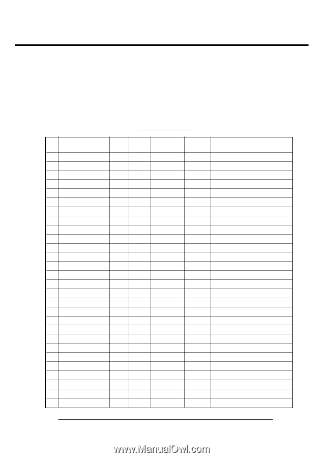
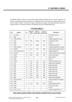
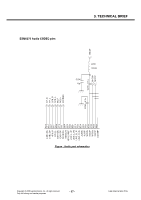
3. TECHNICAL BRIEF The MEGA Camera module is connected to Main PCB with 30pin Board to Board connector Its interface is dedicated camera interface port in Multimedia chip. The camera port supply 13MHz master clock to camera module, vertical sync signal, horizontal sync signal, reset signal and 8bits data from camera module. The camera module is controlled by I2C port from Multimedia chip. [ Pin Description ] No Symbol 1 AF_GND 2 GND 3 VDD_AF(2.8V) 4 SCL 5 GND 6 SDA 7 VDD_SA(2.8V) 8 VSYNC 9 VDD_IO(2.8or1.8V) 10 HSYNC 11 TRIG 12 XRST 13 GND 14 STRB 15 D[7] 16 D[6] 17 D[5] 18 D[4] 19 D[3] 20 D[2] 21 D[1] 22 D[0] 23 VDD_SD(1.8V) 24 GND 25 DCK 26 MCK 27 GND 28 VDD_L(1.2V) I/O State at State at State at reset power save power off - - - - - - - - - - - - I/O HiZ Active HiZ - - - - I/O HiZ Active HiZ - - - - O Low HiZ HiZ - - - - O Low HiZ HiZ O Low Low Low I - - - - - - - O Low Low Low O Low HiZ HiZ O Low HiZ HiZ O Low HiZ HiZ O Low HiZ HiZ O Low HiZ HiZ O Low HiZ HiZ O Low HiZ HiZ O Low HiZ HiZ - - - - - - - - O Low HiZ HiZ I - - - - - - - - - - - Description Ground(Auto Focus) Ground Voltage Supply(Auto Focus) I2C Serial Bus Clock Ground I2C Serial Bus Data I/O Voltage Supply(Sensor Analog) Vertical Synchronization Signal Voltage Supply(I/O) Horizontal Synchronization Signal Interrupt Line Signal System Reset Ground LED/Xenon Strobe Contol Digital Video Data(MSB) Digital Video Data Digital Video Data Digital Video Data Digital Video Data Digital Video Data Digital Video Data Digital Video Data(LSB) Voltage Supply(Sensor Digital) Ground Digital Video Data Clock System Clock Input Ground Voltage Supply(DSP Core) Table. Interface between MEGA Camera Module and MAIN PCB (in camera module) Copyright © 2008 LG Electronics. Inc. All right reserved. Only for training and service purposes - 53 - LGE Internal Use Only
-
 1
1 -
2
-
3
-
4
-
5
-
6
-
7
-
8
-
9
-
10
-
11
-
12
-
13
-
14
-
15
-
16
-
17
-
18
-
19
-
20
-
21
-
22
-
23
-
24
-
25
-
26
-
27
-
28
-
29
-
30
-
31
-
32
-
33
-
34
-
35
-
36
-
37
-
38
-
39
-
40
-
41
-
42
-
43
-
44
-
45
-
46
-
 47
47 -
 48
48 -
 49
49 -
 50
50 -
 51
51 -
 52
52 -
 53
53 -
 54
54 -
 55
55 -
 56
56 -
 57
57 -
58
-
59
-
60
-
61
-
62
-
63
-
64
-
65
-
66
-
67
-
68
-
69
-
70
-
71
-
72
-
73
-
74
-
75
-
76
-
77
-
78
-
79
-
80
-
81
-
82
-
83
-
84
-
85
-
86
-
87
-
88
-
89
-
90
-
91
-
92
-
93
-
94
-
95
-
96
-
97
-
98
-
99
-
100
-
101
-
102
-
103
-
104
-
105
-
106
-
107
-
108
-
109
-
110
-
111
-
112
-
113
-
114
-
115
-
116
-
117
-
118
-
119
-
120
-
121
-
122
-
123
-
124
-
125
-
126
-
127
-
128
-
129
-
130
-
131
-
132
-
133
-
134
-
135
-
136
-
137
-
138
-
139
-
140
-
141
-
142
-
143
-
144
-
145
-
146
-
147
-
148
-
149
-
150
-
151
-
152
-
153
-
154
-
155
-
156
-
157
-
158
-
159
-
160
-
161
-
162
-
163
-
164
-
165
-
166
-
167
-
168
-
169
-
170
-
171
-
172
-
173
-
174
-
175
-
176
-
177
-
178
-
179
-
180
-
181
-
182
-
183
-
184
-
185
-
186
-
187
-
188
-
189
-
190
-
191
-
192
-
193
-
194
-
195
-
196
-
197
-
198
-
199
-
200
-
201
-
202
-
203
-
204
 |
 |