LG KE990 Service Manual - Page 16
GSM Mode
 |
View all LG KE990 manuals
Add to My Manuals
Save this manual to your list of manuals |
Page 16 highlights
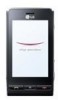
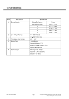
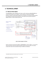
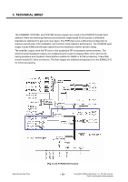
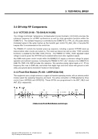
3. TECHNICAL BRIEF 3.2 GSM Mode 3.2.1 GSM Receiver The Dual-mode KE990/KE990c's receiver functions are split between the three RFICs as follows: ■ EGSM-900, DCS-1800 and PCS-1900 modes both use the RTR6235 IC only.Each mode has independent front-end circuits and down-converters, but they share common baseband circuits (with only one mode active at a time). All receiver control functions are beginning with SBI2-controlled parameters. RF Front end consists of antenna, antenna switch module (LMSP43QA-538) which includes four RX saw filters (EGSM-900, DCS-1800 and PCS-1900). The antenna switch module allows multiple operating bands and modes to share the same antenna. In KE990/KE990c, a common antenna connects to one of six paths: 1) GSM 900 Tx (Low Band Tx's share the same path), 2) GSM1800/1900 Tx (High Band Tx's share the same path), 3) EGSM900 Rx, 4) GSM1800 Rx, 5) GSM1900 Rx. EGSM900, DCS1800, and PCS1900 operation is time division duplexed, so only the receiver or transmitter is active at any time and a frequency duplexer is not required. [Table 3.2.1] Antenna Switch Module Control logic The EGSM900, DCS1800, and PCS1900 receiver inputs of RTR6235 are connected directly to the transceiver front-end circuits(filters and antenna switch module). EGSM900, DCS1800, and PCS1900 receiver inputs use differential configurations to improve common-mode rejection and second-order non-linearity performance. The balance between the complementary signals is critical and must be maintained from the RF filter outputs all the way into the IC pins. Since EGSM900, DCS1800, and PCS1900 signals are time-division duplex (the handset can only receive or transmit at one time), switches are used to separate Rx and Tx signals in place of frequency duplexers - this is accomplished in the switch module. 2 The RFIC operating modes and circuit parameters are ESM-controlled through the proprietary 3-line Serial Bus Interface (SBI). The Application Programming Interface (API) is used to implement SBI commands. The API is documented in AMSS Software - please see applicable AMSS Software documentation for details. Copyright © 2008 LG Electronics. Inc. All right reserved. Only for training and service purposes - 17 - LGE Internal Use Only
-
 1
1 -
2
-
3
-
4
-
5
-
6
-
7
-
8
-
9
-
10
-
 11
11 -
 12
12 -
 13
13 -
 14
14 -
 15
15 -
 16
16 -
 17
17 -
 18
18 -
 19
19 -
 20
20 -
 21
21 -
22
-
23
-
24
-
25
-
26
-
27
-
28
-
29
-
30
-
31
-
32
-
33
-
34
-
35
-
36
-
37
-
38
-
39
-
40
-
41
-
42
-
43
-
44
-
45
-
46
-
47
-
48
-
49
-
50
-
51
-
52
-
53
-
54
-
55
-
56
-
57
-
58
-
59
-
60
-
61
-
62
-
63
-
64
-
65
-
66
-
67
-
68
-
69
-
70
-
71
-
72
-
73
-
74
-
75
-
76
-
77
-
78
-
79
-
80
-
81
-
82
-
83
-
84
-
85
-
86
-
87
-
88
-
89
-
90
-
91
-
92
-
93
-
94
-
95
-
96
-
97
-
98
-
99
-
100
-
101
-
102
-
103
-
104
-
105
-
106
-
107
-
108
-
109
-
110
-
111
-
112
-
113
-
114
-
115
-
116
-
117
-
118
-
119
-
120
-
121
-
122
-
123
-
124
-
125
-
126
-
127
-
128
-
129
-
130
-
131
-
132
-
133
-
134
-
135
-
136
-
137
-
138
-
139
-
140
-
141
-
142
-
143
-
144
-
145
-
146
-
147
-
148
-
149
-
150
-
151
-
152
-
153
-
154
-
155
-
156
-
157
-
158
-
159
-
160
-
161
-
162
-
163
-
164
-
165
-
166
-
167
-
168
-
169
-
170
-
171
-
172
-
173
-
174
-
175
-
176
-
177
-
178
-
179
-
180
-
181
-
182
-
183
-
184
-
185
-
186
-
187
-
188
-
189
-
190
-
191
-
192
-
193
-
194
-
195
-
196
-
197
-
198
-
199
-
200
-
201
-
202
-
203
-
204
 |
 |