LG KG270 Service Manual - Page 28
KEYPAD Interface
 |
View all LG KG270 manuals
Add to My Manuals
Save this manual to your list of manuals |
Page 28 highlights
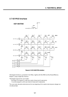
3. TECHNICAL BRIEF 3.7 KEYPAD Interface KEY MATRIX END_KEY END SW200 2V0_VRTC KEY_OUT1 R201 680 C205 NA KEY_OUT2 R203 680 C206 NA KEY_OUT3 R204 680 C207 NA KEY_OUT4 R209 680 C215 NA KEY_IN0 KEY_IN1 KEY_IN2 KEY_IN3 KEY_IN4 R211 680 R212 680 R213 680 R214 680 R215 680 SW201 1 SW206 4 SW211 7 SW216 * C216 NA SW202 2 SW207 5 SW212 8 SW2170 C217 NA SW203 3 SW204 LEFT SW205 MENU SW208 6 SW209 UP SW210 SEL SW213 9 SW214 RIGHT SW215 SEND SW218 # SW219 DOWN C218 NA C219 NA C220 NA Figure 3-7 KEY MAXTRIX Interface The keypad interface is connected to the X-Bus, together with the XBIU and the Shared Memory Register, using a single Bus Interface. The keypad supports two scan modes: • By default, the keypad is a 4x6 scan matrix (4 input and 6 output pins). • To set the keypad to a 5x5 scan matrix (5 input and 5 output pins) The scan mode should be determined at the very beginning of the system start because changes are not allowed later. - 29 -
-
 1
1 -
2
-
3
-
4
-
5
-
6
-
7
-
8
-
9
-
10
-
11
-
12
-
13
-
14
-
15
-
16
-
17
-
18
-
19
-
20
-
21
-
22
-
 23
23 -
 24
24 -
 25
25 -
 26
26 -
 27
27 -
 28
28 -
 29
29 -
 30
30 -
 31
31 -
 32
32 -
 33
33 -
34
-
35
-
36
-
37
-
38
-
39
-
40
-
41
-
42
-
43
-
44
-
45
-
46
-
47
-
48
-
49
-
50
-
51
-
52
-
53
-
54
-
55
-
56
-
57
-
58
-
59
-
60
-
61
-
62
-
63
-
64
-
65
-
66
-
67
-
68
-
69
-
70
-
71
-
72
-
73
-
74
-
75
-
76
-
77
-
78
-
79
-
80
-
81
-
82
-
83
-
84
-
85
-
86
-
87
-
88
-
89
-
90
-
91
-
92
-
93
-
94
-
95
-
96
-
97
-
98
-
99
-
100
-
101
-
102
-
103
-
104
-
105
-
106
-
107
-
108
-
109
-
110
-
111
-
112
-
113
-
114
-
115
-
116
-
117
-
118
-
119
-
120
-
121
-
122
-
123
-
124
-
125
 |
 |
