LG KG270 Service Manual - Page 40
EGold Voice PMU - rx tx
 |
View all LG KG270 manuals
Add to My Manuals
Save this manual to your list of manuals |
Page 40 highlights
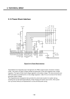
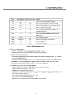
3. TECHNICAL BRIEF Name LRTC LD1 LIO LRFXO LMEM LANA LSIM LBUF LRFRX LRFTRX Output Voltage(V) Output Current (mA) Comment 2.0 4 Used for the real time and digital PMU supply 1.2/1.5 150 Used for the core supplies (MCU and DSP via switch) 1.8/2.85 30 Used for the I/O pad supply and, for example, the display 2.5 10 Used for the crystal oscillator supply 2.5 100 Used for the external memory supply, voltage can be configured during startup 2.5 100 Used for analog (audio and baseband processing) and headset driver 1.8/2.85 30 Used of the SIM card supply 2.6/2.8/3.0/3.2 300 Used for the loudspeaker and earpiece driver 2.5 100 Used for the RF RX part 1.5 120 Used for the RF TX/TX part Figure 3-14-2 EGold Voice PMU LDO output voltage selection • LD1, LIO, LSIM, LBUF output voltage programmable by software. • LMEM output voltage is selectable by pin configuration upon startup. Active and idle power saving options: • The flexible clock switching options allow minimizing the power consumption during the operation phases of the E-GOLDvoice. • Current consumption during the standby mode is minimized by reducing the clock to 32 kHz and switching it off for most of the device. In addition, the power supply for the TEAKLite ROM is switched off and the controller RAM is switched to a power saving mode. Start-up and Reset Control State Machine Features • Power up upon battery insertion, push button, alarm, charger connection. • Detection of battery exchange or re-insertion. • Complete start-up sequence management. • System turn-on, system turn-off operation management including emergency (under-voltage) and programmed shutdown functions. • Internal reset of the baseband, including silent reset. • Tri-state function of the baseband module. • Standby mode controlled by VCXO_EN provided by SCCU module. - 41 -
-
 1
1 -
2
-
3
-
4
-
5
-
6
-
7
-
8
-
9
-
10
-
11
-
12
-
13
-
14
-
15
-
16
-
17
-
18
-
19
-
20
-
21
-
22
-
23
-
24
-
25
-
26
-
27
-
28
-
29
-
30
-
31
-
32
-
33
-
34
-
 35
35 -
 36
36 -
 37
37 -
 38
38 -
 39
39 -
 40
40 -
 41
41 -
 42
42 -
 43
43 -
 44
44 -
 45
45 -
46
-
47
-
48
-
49
-
50
-
51
-
52
-
53
-
54
-
55
-
56
-
57
-
58
-
59
-
60
-
61
-
62
-
63
-
64
-
65
-
66
-
67
-
68
-
69
-
70
-
71
-
72
-
73
-
74
-
75
-
76
-
77
-
78
-
79
-
80
-
81
-
82
-
83
-
84
-
85
-
86
-
87
-
88
-
89
-
90
-
91
-
92
-
93
-
94
-
95
-
96
-
97
-
98
-
99
-
100
-
101
-
102
-
103
-
104
-
105
-
106
-
107
-
108
-
109
-
110
-
111
-
112
-
113
-
114
-
115
-
116
-
117
-
118
-
119
-
120
-
121
-
122
-
123
-
124
-
125
 |
 |
