LG KG270 Service Manual - Page 33
Signals, Description
 |
View all LG KG270 manuals
Add to My Manuals
Save this manual to your list of manuals |
Page 33 highlights
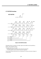
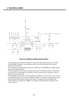
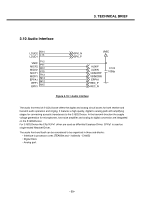
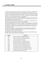
3. TECHNICAL BRIEF The interface to the processor cores consists of a direct physical connection to the TEAKlite DSP bus and a set of firmware commands to handle communication between the C166S and the audio frontend which serves as the interface peripheral for audio algorithms running on the DSP or the controller. The audio front-end Generates interrupts on certain occasions, for example, when exchange of data is requested. The core interface part of the audio front-end also contains the control and status registers which are used to set up certain operation modes of the peripheral. The section next to the core interface contains the digital filters for interpolation and decimation of the audio signals being received and transmitted. The data path for the receive direction can be set up to process sampling rates between 8kHz and 48kHz. The interpolation filters for the respective sampling rates are implemented in a dedi-cated hardware block and are automatically selected to suite the chosen sampling rate. Low-pass interpolation filtering, which produces an unsigned 16-bit data stream with a sampling rate of 4 MHz, is performed digitally. D-to-A conversion, postfiltering, and final amplification are performed on the analog part. The amplifier buffer for voiceband receive does also support ringer functionality. The ringer functionality is activated by Setting bits RINGSELPN or RINGSELPA in the voiceband part of the analog control register. In transmit direction, amplification, prefiltering and A-to-D conversion (analog ∑∆ modulation) are performed on the analog part. The resulting 2-Mbit/s data stream is filtered by a digital low-pass decimation filter for further processing by DSP firmware. Two sampling rates, 8kHz and 16kHz, are supported. The analog section contains all the necessary analog functional blocks including microphone supply generation, output and input amplifiers and analog filtering. Signals EPp1 EPn1 EPpa1 Loud1 Loud2 MICP1 MICN1 MICP2 MICN2 VMIC Description Main Receiver Positive signal(Differential signal) Main Receiver Negative signal(Differential signal) Headset signal(Single Ended signal) Speaker Output Positive signal(Differential signal) Speaker Output Negative signal(Differential signal) Main Microphone Positive signal(Differential signal) Main Microphone Negative signal(Differential signal) Headset Microphone Positive signal(Differential signal) Headset Microphone Negative signal(Differential signal) Main/Headset Microphone supply power - 34 -
-
 1
1 -
2
-
3
-
4
-
5
-
6
-
7
-
8
-
9
-
10
-
11
-
12
-
13
-
14
-
15
-
16
-
17
-
18
-
19
-
20
-
21
-
22
-
23
-
24
-
25
-
26
-
27
-
 28
28 -
 29
29 -
 30
30 -
 31
31 -
 32
32 -
 33
33 -
 34
34 -
 35
35 -
 36
36 -
 37
37 -
 38
38 -
39
-
40
-
41
-
42
-
43
-
44
-
45
-
46
-
47
-
48
-
49
-
50
-
51
-
52
-
53
-
54
-
55
-
56
-
57
-
58
-
59
-
60
-
61
-
62
-
63
-
64
-
65
-
66
-
67
-
68
-
69
-
70
-
71
-
72
-
73
-
74
-
75
-
76
-
77
-
78
-
79
-
80
-
81
-
82
-
83
-
84
-
85
-
86
-
87
-
88
-
89
-
90
-
91
-
92
-
93
-
94
-
95
-
96
-
97
-
98
-
99
-
100
-
101
-
102
-
103
-
104
-
105
-
106
-
107
-
108
-
109
-
110
-
111
-
112
-
113
-
114
-
115
-
116
-
117
-
118
-
119
-
120
-
121
-
122
-
123
-
124
-
125
 |
 |