LG KG270 Service Manual - Page 42
FM Tunner, 15.2 Headphone Amplifier
 |
View all LG KG270 manuals
Add to My Manuals
Save this manual to your list of manuals |
Page 42 highlights
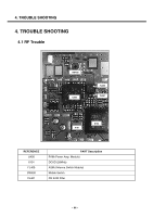
3. TECHNICAL BRIEF 3.15.1 FM Tunner The Si4702 patented digital low-IF architecture reduces external components and eliminates the need for factory adjustments. The receive (RX) section integrates a low noise amplifier (LNA) supporting the worldwide FM broadcast band (76 to 108 MHz). An automatic gain control (AGC) circuit controls the gain of the LNA to optimize sensitivity and rejection of strong interferers. For two-wire operation, a transfer begins with the START condition. The control word is latched internally on rising SCLK edges and is eight bits in length, comprised of a seven bit device address equal to 0010000b and a read/write bit (write = 0 and read = 1). The device acknowledges the address by setting SDIO low on the next falling SCLK edge. For write operations, the device acknowledge Is followed by an eight bit data word latched internally on rising edges of SCLK. The device always acknowledges the data by setting SDIO low on the next falling SCLK edge. An internal address counter automatically increments to allow continuous data byte writes, starting with the upper byte of register 02h, followed by the lower byte of register 02h, and onward until the lower byte of the last register is reached. The internal address counter then automatically wraps around to the upper byte of register 00h and proceeds from there until continuous writes cease. Data transfer ceases with the STOP command. After every STOP Command, The internal address counter is reset. For read operations, the device acknowledge is followed by an eight bit data word shifted out on falling SCLK edges. An internal address counter automatically increments to allow continuous data byte reads, starting with the upper byte of register 0Ah, followed by the lower byte of register 0Ah, and onward until the lower byte of the last register is reached. The internal address counter then automatically wraps around to the upper byte of register 00h and proceeds from there until continuous reads cease. After each byte of data is read, the controller IC should return an acknowledge if an additional byte of data will be requested. Data transfer ceases with the STOP command. After every STOP command, the internal address counter is reset. 3.15.2 Headphone Amplifier The MAX4411 fixed-gain, stereo headphone driver features Maxim's patented DirectDrive architecture, eliminating the large output-coupling capacitors required By conventional single-supply headphone drivers. The device consists of two 80mW Class AB headphone drivers, internal feedback network (fixed -1.5V/V gain), undervoltage lockout (UVLO)/shutdown control, charge pump, and comprehensive click-and-pop suppression circuitry. - 43 -
-
 1
1 -
2
-
3
-
4
-
5
-
6
-
7
-
8
-
9
-
10
-
11
-
12
-
13
-
14
-
15
-
16
-
17
-
18
-
19
-
20
-
21
-
22
-
23
-
24
-
25
-
26
-
27
-
28
-
29
-
30
-
31
-
32
-
33
-
34
-
35
-
36
-
 37
37 -
 38
38 -
 39
39 -
 40
40 -
 41
41 -
 42
42 -
 43
43 -
 44
44 -
 45
45 -
 46
46 -
 47
47 -
48
-
49
-
50
-
51
-
52
-
53
-
54
-
55
-
56
-
57
-
58
-
59
-
60
-
61
-
62
-
63
-
64
-
65
-
66
-
67
-
68
-
69
-
70
-
71
-
72
-
73
-
74
-
75
-
76
-
77
-
78
-
79
-
80
-
81
-
82
-
83
-
84
-
85
-
86
-
87
-
88
-
89
-
90
-
91
-
92
-
93
-
94
-
95
-
96
-
97
-
98
-
99
-
100
-
101
-
102
-
103
-
104
-
105
-
106
-
107
-
108
-
109
-
110
-
111
-
112
-
113
-
114
-
115
-
116
-
117
-
118
-
119
-
120
-
121
-
122
-
123
-
124
-
125
 |
 |