LG KG270 Service Manual - Page 39
Power Block Interface
 |
View all LG KG270 manuals
Add to My Manuals
Save this manual to your list of manuals |
Page 39 highlights
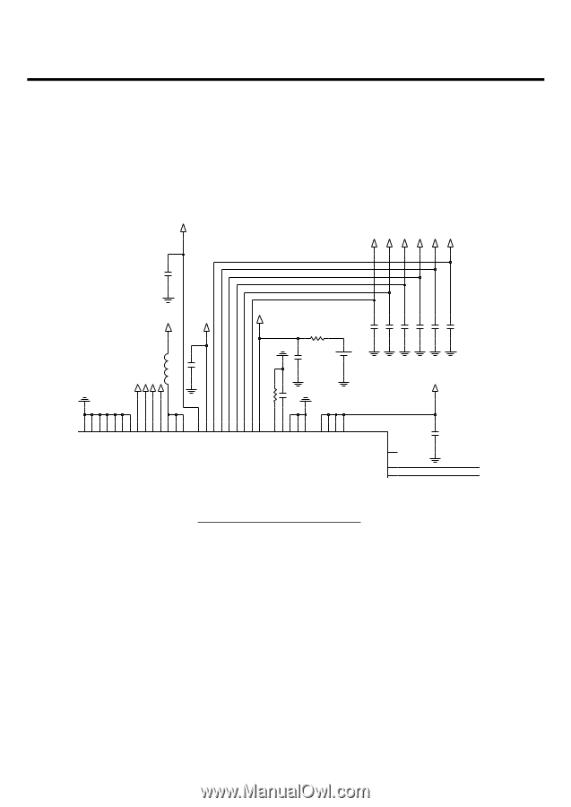
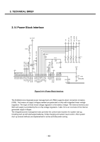
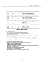
3. TECHNICAL BRIEF 3.14 Power Block Interface VD1 2V8_VIO 2V85_VSIM 2V8_VMEM 1V5_VRF0 3V2_VBUF C101 2.2u VD1 2V5_VANA (1608) L102 18nH C113 1u 2V0_VRTC R100 6.8K BAT100 C112 1u C106 1u C107 1u C108 1u C109 1u C110 1u VRF1 C111 1u VBAT 2V85_VSIM 2V0_VRTC 2V8_VIO 2V8_VMEM IREF G13 C114 220n R101 22K VBAT_1 H13 VBAT_2 F12 H14 H15 J14 J12 G15 G14 K12 VDD_LRTC G12 VDD_LD1 J10 K10 M11 VDD_LRF1V5 B11 J13 K15 F15 VDD_LBUF VDD_MAIN1 G9 VDD_MAIN2 J7 VDD_PLL G10 VDDP_MEM L4 R6 F6 VDDP_IO VDD_RTC R7 B9 B8 VSS2 VSS1 VDD_SIM VSS4 J8 K7 K8 M8 F10 VSS5 VSS8 VSS6 VSS9 VDD_LANA VDD_LRF2V5 VDD_LMEM VDD_LSIM VDD_LIO VREFP AGND W_LED_FBN W_LED_FBP REXT D12 XOX A9 A8 XO Figure 3-14-1 Power Block interface VBAT_4 VBAT_3 C115 2.2u (1608) (16V,K,X5R) The E-GOLDvoice integrated power management unit (PMU) supports direct connection to battery (DCB). That means all supply voltages needed are generated on-chip with integrated linear voltage regulators. The input of these linear voltage regulators is the battery voltage. The external memory and SIM card supply is provided by the on-chip voltage regulators. Table 144 is an overview of the internal generated supply voltages. The integrated power management also provides the control state machine for system start up, including start up with discharged batteries, trickle charging and system reset control. After system start up several methods are implemented for active and idle power saving. - 40 -
-
 1
1 -
2
-
3
-
4
-
5
-
6
-
7
-
8
-
9
-
10
-
11
-
12
-
13
-
14
-
15
-
16
-
17
-
18
-
19
-
20
-
21
-
22
-
23
-
24
-
25
-
26
-
27
-
28
-
29
-
30
-
31
-
32
-
33
-
 34
34 -
 35
35 -
 36
36 -
 37
37 -
 38
38 -
 39
39 -
 40
40 -
 41
41 -
 42
42 -
 43
43 -
 44
44 -
45
-
46
-
47
-
48
-
49
-
50
-
51
-
52
-
53
-
54
-
55
-
56
-
57
-
58
-
59
-
60
-
61
-
62
-
63
-
64
-
65
-
66
-
67
-
68
-
69
-
70
-
71
-
72
-
73
-
74
-
75
-
76
-
77
-
78
-
79
-
80
-
81
-
82
-
83
-
84
-
85
-
86
-
87
-
88
-
89
-
90
-
91
-
92
-
93
-
94
-
95
-
96
-
97
-
98
-
99
-
100
-
101
-
102
-
103
-
104
-
105
-
106
-
107
-
108
-
109
-
110
-
111
-
112
-
113
-
114
-
115
-
116
-
117
-
118
-
119
-
120
-
121
-
122
-
123
-
124
-
125
 |
 |