LG L1404R Service Manual
LG L1404R Manual
 |
View all LG L1404R manuals
Add to My Manuals
Save this manual to your list of manuals |
LG L1404R manual content summary:
- LG L1404R | Service Manual - Page 1
website http://www.lgservice.com LG LG Room Air Conditioner SERVICE MANUAL MODEL: L1404R CAUTION • BEFORE SERVICING THE UNIT, READ THE SAFETY PRECAUTIONS IN THIS MANUAL. • ONLY FOR AUTHORIZED SERVICE PERSONNEL. - LG L1404R | Service Manual - Page 2
Air Conditioner Service Manual TABLE OF CONTENTS Safety Precautions...3 Dimensions ...5 Troubleshooting Guide ...22 Piping System ...22 Troubleshooting Guide ...23 Electrical Parts Troubleshooting Guide ...25 Electric Parts ...29 Exploded View ...35 Replacement Parts List ...36 2 Room Air Conditioner - LG L1404R | Service Manual - Page 3
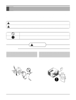
. Be sure not to do. Be sure to follow the instruction. s Installation WARNING Do not use damaged power cord plugs, or a loose socket. Always use the power plug and socket with the ground terminal. • There is risk of fire or electric shock. • There is risk of electric shock. Service Manual 3 - LG L1404R | Service Manual - Page 4
shock, explosion, or injury. Be cautious when unpacking and installing the product. Do not store or use flammable gas or combustibles near the air conditioner. • Sharp edges could cause injury. Be especially careful of the case edges and the fins on the condenser and evaporator. Sharp edges - LG L1404R | Service Manual - Page 5
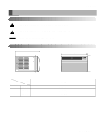
could cause harm to the air conditioner. NOTICE This symbol indicates special notes. Dimensions Outside Dimensions D W Cool Energy Saver F1 LOW 'F F2 MED F3 HIGH Fan Dry Timer TEMP MODE TIMER FAN SPEED POWER H Dimension W H D Model mm(inch) mm(inch) mm(inch) L1404R 660(25 31/32 - LG L1404R | Service Manual - Page 6
Specfications Product Specifications ITEMS MODELS L1404R POWER SUPPLY 1ø, 115V, 60Hz CAPACITY (BTU/h) 13,500 INPUT (W) 26.7(DB)* 19.4(WB)** CONDITION OUTDOOR (°C) 35(DB)* 23.9(WB)** REFRIGERANT (R-22) CHARGE 670g(23.6 oz) EVAPORATOR 2 ROW 11 STACKS, . 6 Room Air Conditioner - LG L1404R | Service Manual - Page 7
(or 20A circuit for Electric Heater Model) 3. To avoid vibration or noise, make sure the air conditioner is installed securely. 4 Avoid placing furniture or draperies in front of the air inlet and outlet. How to Secure the hole of the unit) to fit drain pan to your own unit. Service Manual 7 - LG L1404R | Service Manual - Page 8
12 s Top retainer bar is in the product package. NO. NAME OF PARTS Q'TY 1 FRAME CURTAIN 2 2 SILL SUPPORT 2 3 BOLT 2 4 NUT 2 5 SCREW(TYPE A) (10mm(2/5")) 16 6 SCREW(TYPE B) D5.1mm(0.2")/16mm(0.63 FOAM-PE (920mm x 30mm x 2mm) 1 12 DRAIN PIPE 1 13 FRAME GUIDE 2 8 Room Air Conditioner - LG L1404R | Service Manual - Page 9
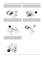
Support Bracket Lock nut Machine screw (Type D) and lock nut Outer edge of window sill Screw(Type B) Sill bracket Top retainer bar Figure 4 Window stool Front angle Window sash Top retainer bar Foam-PE Cabinet Frame curtain Foam-PE Figure 5 Sash track Figure 6 Front Angle Screw(Type B) Service - LG L1404R | Service Manual - Page 10
) 11. Lift the inlet grille and secure it with a screw (Type A) through the front grille. (See Fig. 11) Figure 10 12. Window installation of room air conditioner is now completed. Figure 11 Screw(Type C) Power Cord Screw (Type A) Foam-Strip Window locking bracket 10 Room - LG L1404R | Service Manual - Page 11
air conditioner or if there are obstacles between the Remote Control unit and the air conditioner. POWER BUTTON To turn the air conditioner ON, push the button. To turn the air conditioner 9Hours ➔ 10Hours ➔ 11Hours ➔ 12Hours ➔ off ➔ 1Hour ➔ 2Hours ➔ ... ) 6 REMOCON SIGNAL RECEIVER Service Manual 11 - LG L1404R | Service Manual - Page 12
removal procedure, above. (Refer to the wiring diagram found on page 22 in this manual and on the control box.) TEMP MODE Cool COOL FAN En DRY Saevrgery INDOOR Fan Dry MODE Timer TIMER FFF321HMLIGOEDWH TEMP SPFAENED ˚C POWER 12 Room Air Conditioner Figure 13 Figure 14 Figure 15 - LG L1404R | Service Manual - Page 13
that fasten the brace. 5. Remove the brace. 6. Remove the 2 screws that fasten the air guide upper. 7. Remove the air guide upper.(See Figure 16) 8. Remove the 2 screws that fasten the evaporator. 9. Move the removal procedure. Disassembly Figure 16 Figure 17 Figure 18 Figure 19 Service Manual 13 - LG L1404R | Service Manual - Page 14
Remove the cabinet. (Refer to section 2) 2. Discharge the refrigerant system using a FreonTM Recovery System. If there is no before venting the FreonTM. Leave the valve in place after servicing the system. 3. Remove the overload protector. (Refer to Air Conditioner Figure 20 Figure 21 Figure 22 - LG L1404R | Service Manual - Page 15
(Use only one ground-marked hole for ground connection.) 7. If the supply cord of this appliance is damaged, it must be replaced by the special cord. (The special cord means the cord DESIRED PRFEFUFS3EN2A1RASHAEMULYVITIRGOETRFAEDOWHGIRREYTR TIMER SPFAENED ˚C POWER Figure 24 Service Manual 15 - LG L1404R | Service Manual - Page 16
carefully. (Refer to section 4) 5. After discharging the refrigerant completely, unbraze the interconnecting tube at the evaporator connections. 6. Remove the evaporator. 7. Re-install the components by referring to notes. (See Figure 27) 16 Room Air Conditioner Figure 25 Figure 26 Figure 27 - LG L1404R | Service Manual - Page 17
the refrigerant system using a FreonTM recovery System. If there is no valve to attach the recovery system, install one (such as a WATCO A-1) before venting the FreonTM. Leave the valve in place after servicing the for a while, and then test the leakage of the pinch-off connection. Service Manual 17 - LG L1404R | Service Manual - Page 18
Tools to remove components, Service valve. CONDENSER (HIGH PRESSURE SIDE) COMPOUND GAUGE MANIFOLD GAUGE B A CAPILLARY TUBE SEE INSETS BELOW EVAPORATOR (LOW PRESSURE SIDE) COMPRESSOR A B EXTERNAL VACUUM PUMP Figure 28A-Pulling Vacuum 18 Room Air Conditioner LOW HI B A CHARGING CYLINDER - LG L1404R | Service Manual - Page 19
Schematic Diagram Electronic Control Device Schematic Diagram Service Manual 19 - LG L1404R | Service Manual - Page 20
ASSEMBLY LOCATION NO. DESCRIPTION 1 MOTOR ASSY 2 CAPACITOR 3 COMPRESSOR 4 OVERLOAD PROTECTOR 5 DC PCB ASSEMBLY 6 AC PCB ASSEMBLY 7 THERMISTOR 8 PLASMA FILTER ASSY Q'TY PER SET 1 1 1 1 1 1 1 1 S: Service Parts N: Non Service Parts REMARKS S S S S S S S S 20 Room Air Conditioner - LG L1404R | Service Manual - Page 21
J09 J20 J10 J13 J19 J18 J11 OSC01B IC03G SW02G TEMP DOWN RECEIVER IC01A SW06G TEMP UP C02L C02A BZ01E J24 J2ZD02F J23 J22 J21 Service Manual 21 - LG L1404R | Service Manual - Page 22
OFF POINT SUCTION LINE COOL LOW PRESSURE VAPOR ROOM AIR HEAT LOAD CONDENSER COILS VAPOR INLET HOT DISCHARGED AIR LIQUID PRESSURE DROP 22 Room Air Conditioner MOTOR OUTSIDE COOLING AIR FOR REFRIGERANT PASS THROUGH COMPRESSOR OIL (LIQUID REFRIGERANT) CAPILLARY TUBE Figure 29 LIQUID OUTLET HIGH - LG L1404R | Service Manual - Page 23
Troubleshooting Guide Troubleshooting Guide In general, possible trouble is classified in two kinds. The one is called Starting Failure which is caused from an electrical defect, and the other is ineffective Air Conditioning caused by a defect in the refrigeration circuit and improper application. - LG L1404R | Service Manual - Page 24
Troubleshooting Guide Fails to Start Check of power source. Check of control switch setting. motor resistance ( ) Irregular motor insulation ( ) Replacement of compressor (Motor damaged) 24 Room Air Conditioner Regular but fails to start. Replacement of compressor (locking of rotor, metal). - LG L1404R | Service Manual - Page 25
Electrical Parts Troubleshooting Guide Troubleshooting Guide Possible Trouble 1 The unit does not operate. Is the Trans input power AC 115V? NO (208/230V for LWL1230WAL) •• Is the voltage No.18 of Micom DC 5V? YES Replace AC PCB Ass'y. • Check the PCB pattern. Service Manual 25 - LG L1404R | Service Manual - Page 26
Troubleshooting Guide Possible Trouble 2 The compressor does not operate. Is setting Replace MAIN PCB Ass'y. Possible Trouble 3 The compressor always operate. Is the wire connection of NO RY-COMP OK? YES • Check the RY-COMP. • Connect LEAD Wire to RY-COMP again. 26 Room Air Conditioner - LG L1404R | Service Manual - Page 27
or RY-Lo. • Check the wiring diagram. Troubleshooting Guide • Replace IC01M. • Replace IC01M. Possible Trouble 5 The function of Energy Saver does not operate MANUAL. • Set the mode key to Energy Saver mode. • Check the Energy Saver mode key. • Check the pattern of AC & DC PCB. Service Manual 27 - LG L1404R | Service Manual - Page 28
. Possible Trouble 7 It displays abnormally on DC PCB Ass'y. NO Is the IC01G good? YES NO Is the connection of NO CN-AC/DC OK? YES Does the IC03G (Q01G, Q02G, Q03G for Delux Model) NO operate normally on DC PCB Ass'y? YES • Replace the DC PCB Ass'y. 28 Room Air Conditioner • Replace - LG L1404R | Service Manual - Page 29
ElectrIc Parts Troubleshooting Guide Possible Trouble 1 The unit does not operate. Is the Trans input power AC 115V? NO (208/230V for LWL1230WAL) ••CChheecckktthheeFFuussee.. •• . NO Is the voltage No.40 of Micom DC 5V? YES Replace AC PCB Ass'y. • Check the PCB pattern. Service Manual 29 - LG L1404R | Service Manual - Page 30
Troubleshooting Guide Possible Trouble 2 The compressor does not operate. Is desired Temp Replace AC PCB Ass'y. Possible Trouble 3 The compressor always operate. Is the wire connection of NO RY-COMP OK? YES • Check the RY-COMP. • Connect LEAD Wire to RY-COMP again. 30 Room Air Conditioner - LG L1404R | Service Manual - Page 31
NO of CN-AC/DC on AC PCB Ass'y DC 5V? YES Is the connection of NO CN-AC/DC OK? YES • Replace Receiver Ass'y. Troubleshooting Guide • Replace IC01M. • Replace IC01M. • Replace the battery. ••CChheecckk tthheePPCCBBpaptatettrenr.n. • Connect connector to CN-AC/DC exactly. Service Manual 31 - LG L1404R | Service Manual - Page 32
Troubleshooting Guide Possible Trouble 6 It displays abnormally on DC PCB Ass'y. NO Are the IC01G and IC02G good? YES NO Is the connection of NO 'y? YES • Replace the DC PCB Ass'y. • Replace IC01G, IC02G. • Connect connector to CN-AC/DC exactly. • Replace IC03G. 32 Room Air Conditioner - LG L1404R | Service Manual - Page 33
Troubleshooting Guide COMPLAINT Fan motor will not run. Fan motor runs intermittently Fan motor noise. Compressor will not run, but fan motor runs. If wires are off, refer to wiring diagram for identification, and replace. Check wire locations. If not per wiring diagram, correct. Service Manual 33 - LG L1404R | Service Manual - Page 34
Troubleshooting Guide COMPLAINT CAUSE REMEDY Compressor will not run, but fan motor runs. Thermistor Capacitor (Discharge capacitor before servicing.) Compressor Overload Compressor cycles on overload. Voltage Overload Compressor cycles on overload. Fan motor Condenser air flow restriction - LG L1404R | Service Manual - Page 35
Timer TIMER F1 F2 F3 LMHOIEGWDH TEMP SPFAENED ˚C POWER TEMP POWER 237200 263230 W0CZZ 135500 567502 554160 249950 550140 W52106-1 352111 W52106-2 264110 35211A 352113 Service Manual 35 - LG L1404R | Service Manual - Page 36
GUIDE ASSEMBLY EVAPORATOR ASSEMBLY, FIRST ISOLATOR, COMP CONDENSER ASSEMBLY, FIRST COMPRESSOR SET FAN ASSEMBLY, AXIAL FAN ASSEMBLY, TURBO REMOTE CONTROLLER ASSEMBLY CLAMP, SPRING CAPACITOR, DRAWING Replacement Parts List PART NO. L1404R R R R R R R R R R R R R R R R R R R R 36 Room Air Conditioner - LG L1404R | Service Manual - Page 37
Memo Service Manual 37 - LG L1404R | Service Manual - Page 38
Memo 38 Room Air Conditioner - LG L1404R | Service Manual - Page 39
P/No.: 3828A20306U June, 2004 Printed in Korea
-
 1
1 -
 2
2 -
 3
3 -
 4
4 -
 5
5 -
 6
6 -
 7
7 -
8
-
9
-
10
-
11
-
12
-
13
-
14
-
15
-
16
-
17
-
18
-
19
-
20
-
21
-
22
-
23
-
24
-
25
-
26
-
27
-
28
-
29
-
30
-
31
-
32
-
33
-
34
-
35
-
36
-
37
-
38
-
39
 |
 |

LG
Room
Air Conditioner
SERVICE MANUAL
LG
MODEL: L1404R
CAUTION
website http://www.lgservice.com
• BEFORE SERVICING THE UNIT, READ THE SAFETY
PRECAUTIONS IN THIS MANUAL.
• ONLY FOR AUTHORIZED SERVICE PERSONNEL.