LG L1404R Service Manual - Page 16
Refrigerating Cycle
 |
View all LG L1404R manuals
Add to My Manuals
Save this manual to your list of manuals |
Page 16 highlights
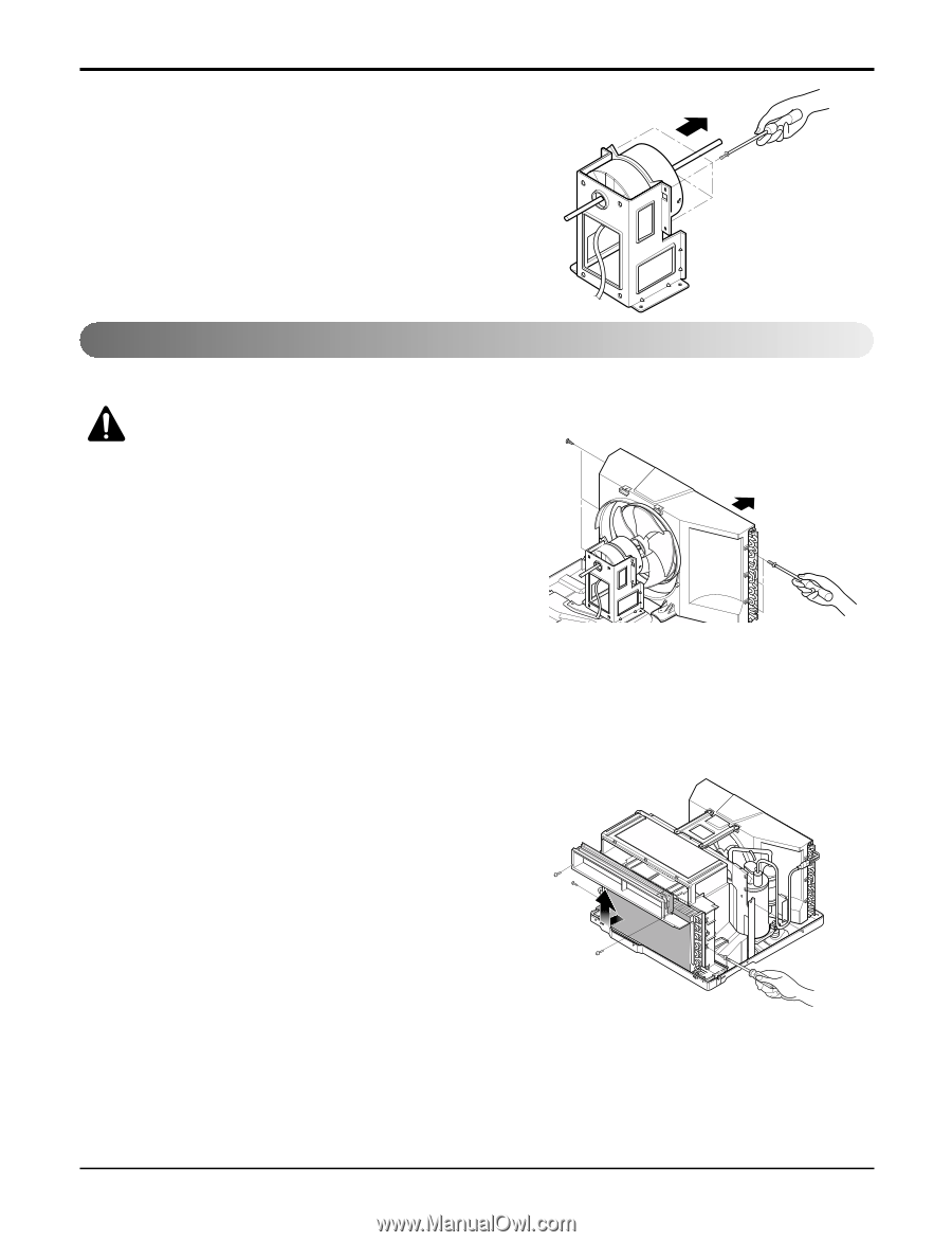
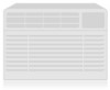
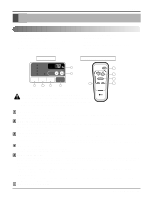
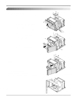
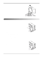
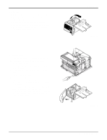
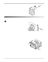
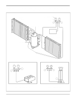
Disassembly 11. Motor 1. Remove the cabinet. (Refer to section 2) 2. Remove the turbo fan. (Refer to section 4) 3. Remove the fan. (Refer to section 5) 4. Remove the 4 screws that fasten the motor from the air guide. (See Figure 25) 5. Remove the motor. 6. Re-install the components by referring to the removal procedure, above.(See Figure 25) Refrigerating Cycle 12. Condenser CAUTION: Discharge the refrigerant system using a FreonTM Recovery System. If there is no valve to attach the recovery system, install one (such as a WATCO A-1) before venting the FreonTM. Leave the valve in place after servicing the system. 1. Remove the cabinet. (Refer to section 2) 2. Remove the 4 screws that fasten the brace.(Refer to section 4) 3. Remove the 5 screws that fasten the condenser and shroud. 4. After discharging the refrigerant completely, unbraze the interconnecting tube at the condenser connections. 5. Remove the condenser. 6. Re-install the components by referring to notes. (See Figure 26) 13. Evaporator 1. Remove the control box.(Refer to section 3) 2. Remove the air guide upper. (Refer to section 4) 3. Remove the 2 screws that fasten the evapora- tor. 4. Move the evaporator sideways carefully. (Refer to section 4) 5. After discharging the refrigerant completely, unbraze the interconnecting tube at the evaporator connections. 6. Remove the evaporator. 7. Re-install the components by referring to notes. (See Figure 27) 16 Room Air Conditioner Figure 25 Figure 26 Figure 27
-
 1
1 -
2
-
3
-
4
-
5
-
6
-
7
-
8
-
9
-
10
-
 11
11 -
 12
12 -
 13
13 -
 14
14 -
 15
15 -
 16
16 -
 17
17 -
 18
18 -
 19
19 -
 20
20 -
 21
21 -
22
-
23
-
24
-
25
-
26
-
27
-
28
-
29
-
30
-
31
-
32
-
33
-
34
-
35
-
36
-
37
-
38
-
39
 |
 |