LG L1404R Service Manual - Page 15
Service Manual, Disassembly - appliances
 |
View all LG L1404R manuals
Add to My Manuals
Save this manual to your list of manuals |
Page 15 highlights
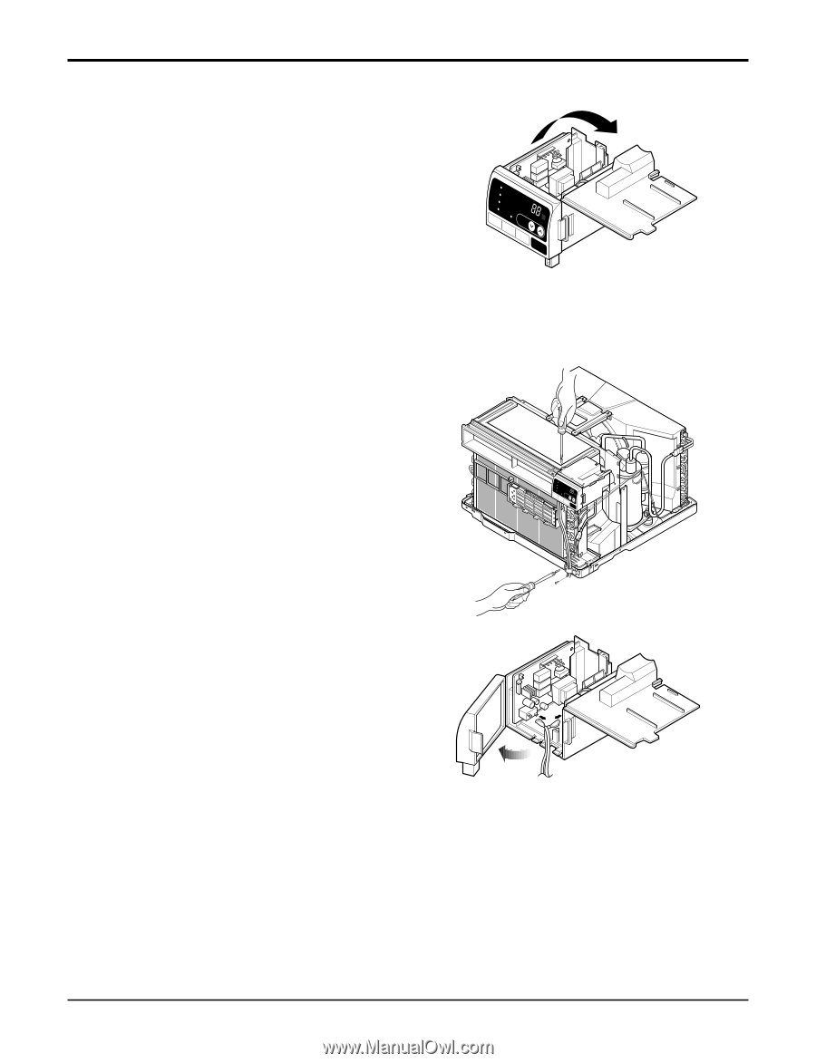
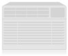
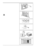
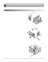
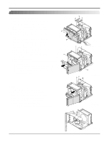
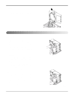
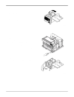
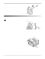
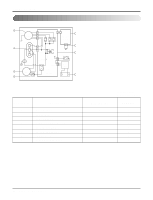
9. Capacitor 1. Remove the control box. (Refer to section 3) 2. Open the top cover from the control box. (See Figure 23) 3. Pull out the capacitor from the control box. 4. Disconnect all the leads of capacitor terminals. 5. Re-install the components by referring to the removal procedure, above. TEMP MODE CoolCOOL FAN Ene DRY SFavrgery INDOOR FAN HEAT DEFROST Drayn Timer DESIRED PRFEFFUS3E2NA1RAHSAMEULYVITIGOERTRFAEDWHOGIRREYTR TIMER SPFAENED ˚C POWER Disassembly Figure 23 10. Power Cord 1. Remove the control box. (Refer to section 3) 2. Open the top cover from the control box. (Refer to section 9) 3. Disconnect the front panel from the control box. (See Figure 24) 4. Disconnect two leads from the capacitor and relay. 5. Pull out the power cord. 6. Re-install the component by referring to the above removal procedure, above. (Use only one ground-marked hole for ground connection.) 7. If the supply cord of this appliance is damaged, it must be replaced by the special cord. (The special cord means the cord which has the same specification marked on the supply cord attached at the unit.) TEMP MODE CoolCOOL FAN Ene DRY SFavrgery INDOOR FAN HEAT DEFROST Drayn Timer DESIRED PRFEFUFS3EN2A1RASHAEMULYVITIRGOETRFAEDOWHGIRREYTR TIMER SPFAENED ˚C POWER Figure 24 Service Manual 15
-
 1
1 -
2
-
3
-
4
-
5
-
6
-
7
-
8
-
9
-
 10
10 -
 11
11 -
 12
12 -
 13
13 -
 14
14 -
 15
15 -
 16
16 -
 17
17 -
 18
18 -
 19
19 -
 20
20 -
21
-
22
-
23
-
24
-
25
-
26
-
27
-
28
-
29
-
30
-
31
-
32
-
33
-
34
-
35
-
36
-
37
-
38
-
39
 |
 |