LG WKEX200HWA Owners Manual - Page 19
Venting the Dryer
 |
View all LG WKEX200HWA manuals
Add to My Manuals
Save this manual to your list of manuals |
Page 19 highlights
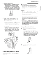
ENGLISH INSTALLATION 19 the male end of the duct protrudes 1 1/2" (3.8 cm) to connect the remaining ductwork. Attach the cover plate f to the back of the dryer with the included screw. f e Venting the Dryer WARNING • Gas dryers MUST exhaust to the outdoors. • DO NOT use sheet metal screws or other fasteners which extend into the duct that could catch lint and reduce the efficiency of the exhaust system. Secure all joints with duct tape. • To reduce the risk of fire, combustion, or accumulation of combustible gases, DO NOT exhaust dryer air into an enclosed and unventilated area, such as an attic, wall, ceiling, crawl space, chimney, gas vent, or concealed space of a building. • To reduce the risk of fire, DO NOT exhaust the dryer with plastic or thin foil ducting. • Do not exceed the recommended duct length limitations noted in the chart. Failure to follow these instructions may result in extended drying times, fire or death. • Do not crush or collapse ductwork. • Do not allow ductwork to rest on or contact sharp objects. • If connecting to existing ductwork, make sure it is suitable and clean before installing the dryer. • Venting must conform to local building codes. • Use only 4 '' (10 cm) rigid, semi-rigid or flexible metal ductwork inside the dryer cabinet and for venting outside. • The exhaust duct must be 4 '' (10 cm) in diameter with no obstructions. The exhaust duct should be kept as short as possible. Make sure to clean any old ducts before installing your new dryer. • Rigid, semi-rigid or flexible metal ducting is recommended for use between the dryer and the wall. All non-rigid metal transition duct must be UL-listed. Use of other materials for transition duct could affect drying time. • Ductwork is not provided with the dryer. You should obtain the necessary ductwork locally. The vent hood should have hinged dampers to prevent backdraft when the dryer is not in use. • The total length of flexible metal duct must not exceed 8 ft. (2.4 m). Ductwork Wall Cap Type Recommended a a a: 4 '' (10 cm) Use for only short run installations b b: 2 1/2 '' (6.4 cm) Number of 90° Elbows 0 1 2 3 4 0 1 2 3 4 Maximum length of 4-inch diameter rigid metal duct 65 ft. (19.8 m) 55 ft. (16.8 m) 47 ft. (14.3 m) 36 ft. (11.0 m) 28 ft. (8.5 m) 55 ft. (16.8 m) 47 ft. (14.3 m) 41 ft. (12.5 m) 30 ft. (9.1 m) 22 ft. (6.7 m) NOTE • Deduct 6 ft. (1.8 m) for each additional elbow. Do not use more than four 90° elbows.
-
 1
1 -
2
-
3
-
4
-
5
-
6
-
7
-
8
-
9
-
10
-
11
-
12
-
13
-
 14
14 -
 15
15 -
 16
16 -
 17
17 -
 18
18 -
 19
19 -
 20
20 -
 21
21 -
 22
22 -
 23
23 -
 24
24 -
25
-
26
-
27
-
28
-
29
-
30
-
31
-
32
-
33
-
34
-
35
-
36
-
37
-
38
-
39
-
40
-
41
-
42
-
43
-
44
-
45
-
46
-
47
-
48
-
49
-
50
-
51
-
52
-
53
-
54
-
55
-
56
-
57
-
58
-
59
-
60
-
61
-
62
-
63
-
64
-
65
-
66
-
67
-
68
-
69
-
70
-
71
-
72
-
73
-
74
-
75
-
76
-
77
-
78
-
79
-
80
-
81
-
82
-
83
-
84
-
85
-
86
-
87
-
88
-
89
-
90
-
91
-
92
-
93
-
94
-
95
-
96
-
97
-
98
-
99
-
100
-
101
-
102
-
103
-
104
-
105
-
106
-
107
-
108
-
109
-
110
-
111
-
112
-
113
-
114
-
115
-
116
-
117
-
118
-
119
-
120
-
121
-
122
-
123
-
124
-
125
-
126
-
127
-
128
-
129
-
130
-
131
-
132
-
133
-
134
-
135
-
136
-
137
-
138
-
139
-
140
-
141
-
142
-
143
-
144
-
145
-
146
-
147
-
148
-
149
-
150
-
151
-
152
-
153
-
154
-
155
-
156
-
157
-
158
-
159
-
160
-
161
-
162
-
163
-
164
-
165
-
166
-
167
-
168
-
169
-
170
-
171
-
172
-
173
-
174
-
175
-
176
-
177
-
178
-
179
-
180
-
181
-
182
-
183
-
184
-
185
-
186
-
187
-
188
-
189
-
190
-
191
-
192
-
193
-
194
-
195
 |
 |
