Lenovo 43192NF User Manual - Page 105
DIMM (upper slot), but not in SLOT-1
 |
View all Lenovo 43192NF manuals
Add to My Manuals
Save this manual to your list of manuals |
Page 105 highlights
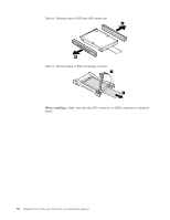
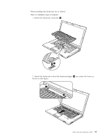
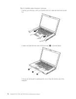
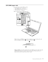
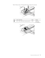
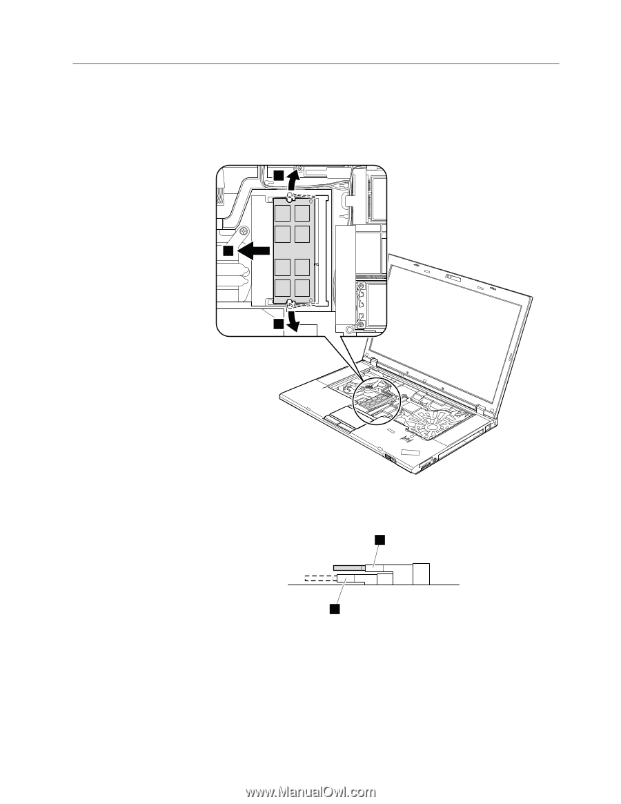
1070 DIMM (upper slot) For access, remove these FRUs in order: v "1010 Battery pack" on page 87 v "1030 DIMM slot cover" on page 89 v "1060 Keyboard" on page 93 Table 19. Removal steps of DIMM (upper slot) 1 2 1 Note: If only one DIMM is used on the computer you are servicing, the card must be installed in SLOT-0 ( a ), but not in SLOT-1 ( b ). a b When installing: Insert the notched end of the DIMM into the socket. Press the DIMM firmly, and pivot it until it snaps into the place. Make sure that it is firmly fixed in the slot and does not move easily. Removing and replacing a FRU 97
-
 1
1 -
2
-
3
-
4
-
5
-
6
-
7
-
8
-
9
-
10
-
11
-
12
-
13
-
14
-
15
-
16
-
17
-
18
-
19
-
20
-
21
-
22
-
23
-
24
-
25
-
26
-
27
-
28
-
29
-
30
-
31
-
32
-
33
-
34
-
35
-
36
-
37
-
38
-
39
-
40
-
41
-
42
-
43
-
44
-
45
-
46
-
47
-
48
-
49
-
50
-
51
-
52
-
53
-
54
-
55
-
56
-
57
-
58
-
59
-
60
-
61
-
62
-
63
-
64
-
65
-
66
-
67
-
68
-
69
-
70
-
71
-
72
-
73
-
74
-
75
-
76
-
77
-
78
-
79
-
80
-
81
-
82
-
83
-
84
-
85
-
86
-
87
-
88
-
89
-
90
-
91
-
92
-
93
-
94
-
95
-
96
-
97
-
98
-
99
-
 100
100 -
 101
101 -
 102
102 -
 103
103 -
 104
104 -
 105
105 -
 106
106 -
 107
107 -
 108
108 -
 109
109 -
 110
110 -
111
-
112
-
113
-
114
-
115
-
116
-
117
-
118
-
119
-
120
-
121
-
122
-
123
-
124
-
125
-
126
-
127
-
128
-
129
-
130
-
131
-
132
-
133
-
134
-
135
-
136
-
137
-
138
-
139
-
140
-
141
-
142
-
143
-
144
-
145
-
146
-
147
-
148
-
149
-
150
-
151
-
152
-
153
-
154
-
155
-
156
-
157
-
158
-
159
-
160
-
161
-
162
-
163
-
164
-
165
-
166
-
167
-
168
-
169
-
170
-
171
-
172
-
173
-
174
-
175
-
176
-
177
-
178
-
179
-
180
-
181
-
182
-
183
-
184
-
185
-
186
-
187
-
188
-
189
-
190
-
191
-
192
-
193
-
194
-
195
-
196
-
197
-
198
-
199
-
200
-
201
-
202
-
203
-
204
-
205
-
206
-
207
-
208
-
209
-
210
-
211
-
212
 |
 |
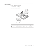
1070 DIMM (upper slot)
For access, remove these FRUs in order:
v
“1010 Battery pack” on page 87
v
“1030 DIMM slot cover” on page 89
v
“1060 Keyboard” on page 93
Table 19. Removal steps of DIMM (upper slot)
1
1
2
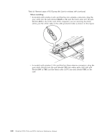
Note:
If only one DIMM is used on the computer you are servicing, the card
must be installed in SLOT-0 (
±a²
), but not in SLOT-1 (
±b²
).
a
b
When installing:
Insert the notched end of the DIMM into the socket. Press the
DIMM firmly, and pivot it until it snaps into the place. Make sure that it is
firmly fixed in the slot and does not move easily.
Removing and replacing a FRU
97