Lenovo 43192NF User Manual - Page 133
System board assembly and magnesium structure frame, Important notices for RAID setting, Config
 |
View all Lenovo 43192NF manuals
Add to My Manuals
Save this manual to your list of manuals |
Page 133 highlights
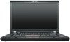
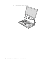
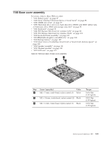
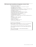
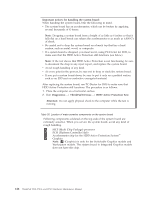
1200 System board assembly and magnesium structure frame For access, remove these FRUs in order: v "1010 Battery pack" on page 87 v "1020 Serial Ultrabay Enhanced device or travel bezel" on page 88 v "1030 DIMM slot cover" on page 89 v "1040 DIMM (bottom slot)" on page 90 v "1050 Hard disk drive slot cover, hard disk drive (HDD) and HDD rubber rails or Solid state drive (SSD) and storage converter" on page 91 v "1060 Keyboard" on page 93 v "1070 DIMM (upper slot)" on page 97 v "1080 PCI Express Mini Card for wireless LAN" on page 98 v "1090 PCI Express Mini Card for wireless WAN" on page 101 v "1100 Keyboard bezel assembly" on page 103 v "1110 Bluetooth daughter card (BDC-2.1)" on page 106 v "1120 Backup battery" on page 107 v "1130 Smart Card or Contactless Smart Card or Smart Card dummy spacer" on page 108 v "1140 Speaker assembly" on page 111 v "1150 Thermal module" on page 113 v "1160 CPU" on page 116 v "1170 LCD unit" on page 117 v "1180 Base cover assembly" on page 121 v "1190 I/O sub card" on page 124 Important notices for RAID setting: Before you replace the system board, make sure that you read "Installing and configuring RAID" on page 71, and have the necessary information. After you replaced the system board, RAID mode is recovered as default. To confirm the SATA mode setting, you can see the setting in BIOS Setup Utility menu as follows: Config -> Serial ATA (SATA) -> SATA Controller Mode Option -> Compatibility/AHCI/RAID Removing and replacing a FRU 125
-
 1
1 -
2
-
3
-
4
-
5
-
6
-
7
-
8
-
9
-
10
-
11
-
12
-
13
-
14
-
15
-
16
-
17
-
18
-
19
-
20
-
21
-
22
-
23
-
24
-
25
-
26
-
27
-
28
-
29
-
30
-
31
-
32
-
33
-
34
-
35
-
36
-
37
-
38
-
39
-
40
-
41
-
42
-
43
-
44
-
45
-
46
-
47
-
48
-
49
-
50
-
51
-
52
-
53
-
54
-
55
-
56
-
57
-
58
-
59
-
60
-
61
-
62
-
63
-
64
-
65
-
66
-
67
-
68
-
69
-
70
-
71
-
72
-
73
-
74
-
75
-
76
-
77
-
78
-
79
-
80
-
81
-
82
-
83
-
84
-
85
-
86
-
87
-
88
-
89
-
90
-
91
-
92
-
93
-
94
-
95
-
96
-
97
-
98
-
99
-
100
-
101
-
102
-
103
-
104
-
105
-
106
-
107
-
108
-
109
-
110
-
111
-
112
-
113
-
114
-
115
-
116
-
117
-
118
-
119
-
120
-
121
-
122
-
123
-
124
-
125
-
126
-
127
-
 128
128 -
 129
129 -
 130
130 -
 131
131 -
 132
132 -
 133
133 -
 134
134 -
 135
135 -
 136
136 -
 137
137 -
 138
138 -
139
-
140
-
141
-
142
-
143
-
144
-
145
-
146
-
147
-
148
-
149
-
150
-
151
-
152
-
153
-
154
-
155
-
156
-
157
-
158
-
159
-
160
-
161
-
162
-
163
-
164
-
165
-
166
-
167
-
168
-
169
-
170
-
171
-
172
-
173
-
174
-
175
-
176
-
177
-
178
-
179
-
180
-
181
-
182
-
183
-
184
-
185
-
186
-
187
-
188
-
189
-
190
-
191
-
192
-
193
-
194
-
195
-
196
-
197
-
198
-
199
-
200
-
201
-
202
-
203
-
204
-
205
-
206
-
207
-
208
-
209
-
210
-
211
-
212
 |
 |