Lenovo 43192NF User Manual - Page 141
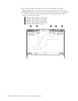
When attaching the LCD panel to the cover, press the left
 |
View all Lenovo 43192NF manuals
Add to My Manuals
Save this manual to your list of manuals |
Page 141 highlights
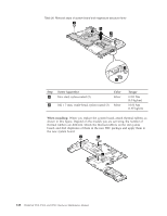
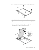
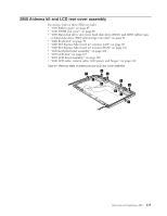
Table 40. Removal steps of LCD cable, camera cable, LCD panel, and hinges (continued) 2 2 2 2 Step 2 Screw (quantity) Color M2.5 × 6 mm, wafer-head, nylon-coated (4) Black Torque 0.392 Nm (4.0 kgfcm) When installing: When attaching the LCD panel to the cover, press the left and right edges covered with metal gently with your fingers. DO NOT press the surface of the panel or apply any excessive force to the panel. 3 4 5 5 5 Removing and replacing a FRU 133
-
 1
1 -
2
-
3
-
4
-
5
-
6
-
7
-
8
-
9
-
10
-
11
-
12
-
13
-
14
-
15
-
16
-
17
-
18
-
19
-
20
-
21
-
22
-
23
-
24
-
25
-
26
-
27
-
28
-
29
-
30
-
31
-
32
-
33
-
34
-
35
-
36
-
37
-
38
-
39
-
40
-
41
-
42
-
43
-
44
-
45
-
46
-
47
-
48
-
49
-
50
-
51
-
52
-
53
-
54
-
55
-
56
-
57
-
58
-
59
-
60
-
61
-
62
-
63
-
64
-
65
-
66
-
67
-
68
-
69
-
70
-
71
-
72
-
73
-
74
-
75
-
76
-
77
-
78
-
79
-
80
-
81
-
82
-
83
-
84
-
85
-
86
-
87
-
88
-
89
-
90
-
91
-
92
-
93
-
94
-
95
-
96
-
97
-
98
-
99
-
100
-
101
-
102
-
103
-
104
-
105
-
106
-
107
-
108
-
109
-
110
-
111
-
112
-
113
-
114
-
115
-
116
-
117
-
118
-
119
-
120
-
121
-
122
-
123
-
124
-
125
-
126
-
127
-
128
-
129
-
130
-
131
-
132
-
133
-
134
-
135
-
 136
136 -
 137
137 -
 138
138 -
 139
139 -
 140
140 -
 141
141 -
 142
142 -
 143
143 -
 144
144 -
 145
145 -
 146
146 -
147
-
148
-
149
-
150
-
151
-
152
-
153
-
154
-
155
-
156
-
157
-
158
-
159
-
160
-
161
-
162
-
163
-
164
-
165
-
166
-
167
-
168
-
169
-
170
-
171
-
172
-
173
-
174
-
175
-
176
-
177
-
178
-
179
-
180
-
181
-
182
-
183
-
184
-
185
-
186
-
187
-
188
-
189
-
190
-
191
-
192
-
193
-
194
-
195
-
196
-
197
-
198
-
199
-
200
-
201
-
202
-
203
-
204
-
205
-
206
-
207
-
208
-
209
-
210
-
211
-
212
 |
 |
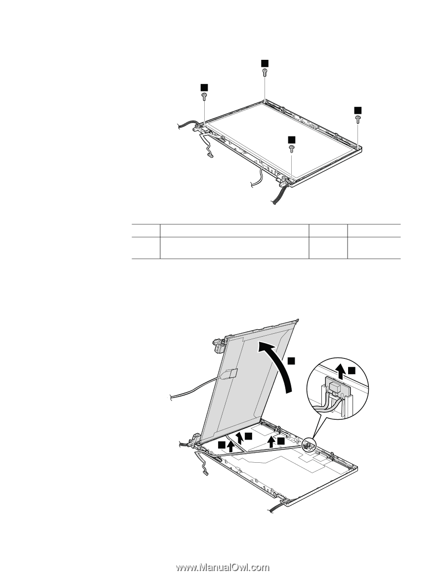
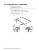
Table 40. Removal steps of LCD cable, camera cable, LCD panel, and hinges (continued)
2
2
2
2
Step
Screw (quantity)
Color
Torque
±2²
M2.5
×
6 mm, wafer-head, nylon-coated (4)
Black
0.392 Nm
(4.0 kgfcm)
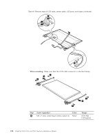
When installing:
When attaching the LCD panel to the cover, press the left and
right edges covered with metal gently with your fingers. DO NOT press the
surface of the panel or apply any excessive force to the panel.
4
5
5
5
3
Removing and replacing a FRU
133