Lenovo B460 Lenovo B460 Hardware Maintenance Manual V2.0 - Page 56
Improper placement of, the switch or those jacks might cause a damage.
 |
View all Lenovo B460 manuals
Add to My Manuals
Save this manual to your list of manuals |
Page 56 highlights
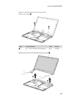
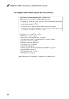
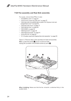
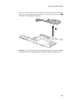
IdeaPad B460 Hardware Maintenance Manual Figure 11. Removal steps of system board, ExpressCard slot assembly (continued) Unplug the power connector and USB connector in the direction shown by arrow 3, and then remove the system board in the direction shown by arrow 4. 4 3 a a When installing: When attaching the system board to the base cover, adjust the placement of the wireless radio switch and the graphics switch as shown in b , and make sure that both of the audio jack and the microphone jack are attached to the holes on the base cover as shown in a . Improper placement of the switch or those jacks might cause a damage. 52
-
 1
1 -
2
-
3
-
4
-
5
-
6
-
7
-
8
-
9
-
10
-
11
-
12
-
13
-
14
-
15
-
16
-
17
-
18
-
19
-
20
-
21
-
22
-
23
-
24
-
25
-
26
-
27
-
28
-
29
-
30
-
31
-
32
-
33
-
34
-
35
-
36
-
37
-
38
-
39
-
40
-
41
-
42
-
43
-
44
-
45
-
46
-
47
-
48
-
49
-
50
-
 51
51 -
 52
52 -
 53
53 -
 54
54 -
 55
55 -
 56
56 -
 57
57 -
 58
58 -
 59
59 -
 60
60 -
 61
61 -
62
-
63
-
64
-
65
-
66
-
67
-
68
-
69
-
70
-
71
-
72
-
73
-
74
-
75
-
76
-
77
-
78
-
79
-
80
-
81
-
82
-
83
-
84
-
85
-
86
-
87
-
88
 |
 |

52
IdeaPad B460 Hardware Maintenance Manual
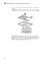
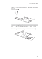
Figure 11. Removal steps of system board, ExpressCard slot assembly
(continued)
Unplug the power connector and USB connector in the direction shown by
arrow
3
, and then remove the system board in the direction shown by arrow
4
.
4
a
a
3
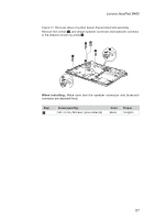
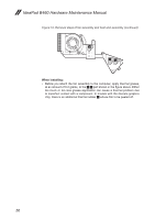
When installing:
When attaching the system board to the base cover, adjust
the placement of the wireless radio switch and the graphics switch as shown
in
b
, and make sure that both of the audio jack and the microphone jack are
attached to the holes on the base cover as shown in
a
. Improper placement of
the switch or those jacks might cause a damage.