Lenovo IdeaPad Z360 Lenovo IdeaPad Z360 Hardware Maintenance Manual - Page 48
Attention, Removal steps of fan assembly and heat sink assembly continued
 |
View all Lenovo IdeaPad Z360 manuals
Add to My Manuals
Save this manual to your list of manuals |
Page 48 highlights
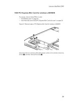
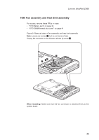
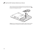
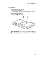
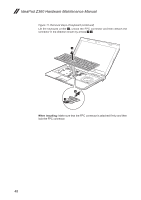
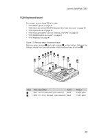
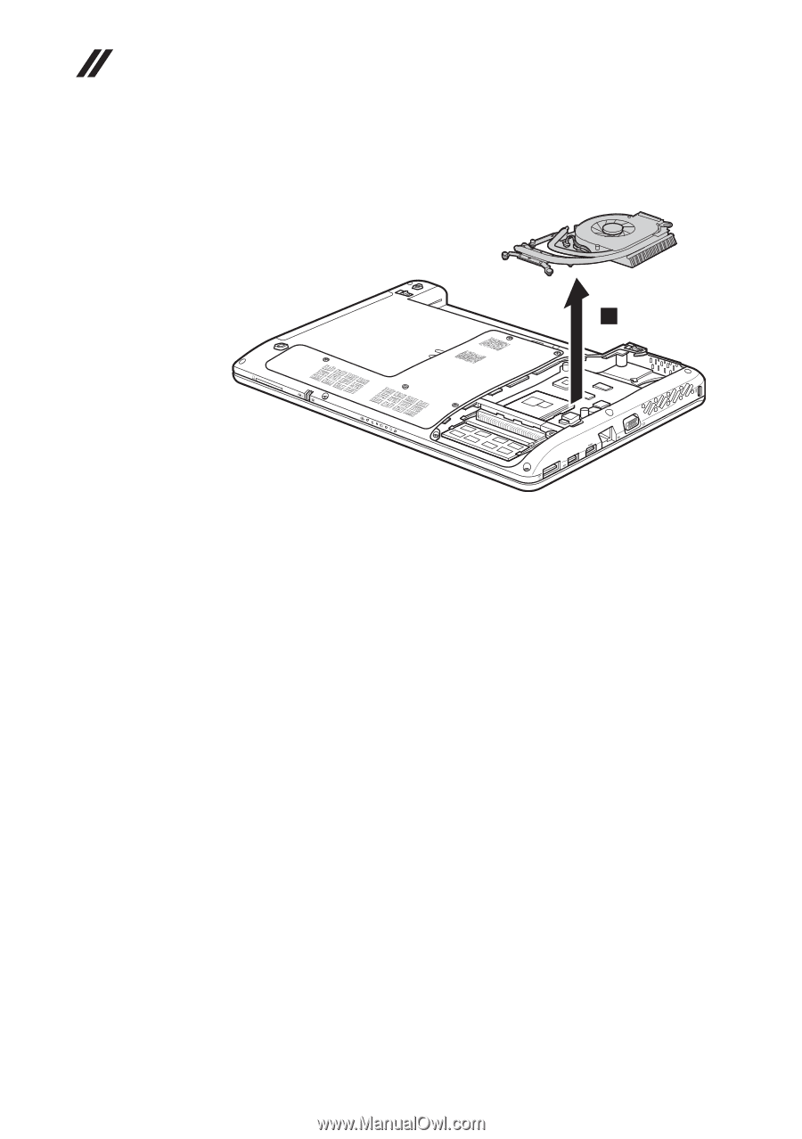
IdeaPad Z360 Hardware Maintenance Manual Figure 9. Removal steps of fan assembly and heat sink assembly (continued) Lift the fan assembly and heat sink assembly in the direction shown by arrow 3. Be careful not to damage the connector. 3 Attention: Do not handle the heat sink assembly roughly. Improper handling can cause distortion or deformation and imperfect contact with components. 44
-
 1
1 -
2
-
3
-
4
-
5
-
6
-
7
-
8
-
9
-
10
-
11
-
12
-
13
-
14
-
15
-
16
-
17
-
18
-
19
-
20
-
21
-
22
-
23
-
24
-
25
-
26
-
27
-
28
-
29
-
30
-
31
-
32
-
33
-
34
-
35
-
36
-
37
-
38
-
39
-
40
-
41
-
42
-
 43
43 -
 44
44 -
 45
45 -
 46
46 -
 47
47 -
 48
48 -
 49
49 -
 50
50 -
 51
51 -
 52
52 -
 53
53 -
54
-
55
-
56
-
57
-
58
-
59
-
60
-
61
-
62
-
63
-
64
-
65
-
66
-
67
-
68
-
69
-
70
-
71
-
72
-
73
-
74
-
75
-
76
-
77
-
78
-
79
-
80
-
81
-
82
-
83
-
84
-
85
-
86
-
87
-
88
-
89
 |
 |
44
IdeaPad Z360 Hardware Maintenance Manual
Figure 9. Removal steps of fan assembly and heat sink assembly (continued)
Lift the fan assembly and heat sink assembly in the direction shown by arrow
3
.
Be careful not to damage the connector.
3
Attention:
Do not handle the heat sink assembly roughly. Improper handling
can cause distortion or deformation and imperfect contact with components.