Lenovo IdeaPad Z360 Lenovo IdeaPad Z360 Hardware Maintenance Manual - Page 68
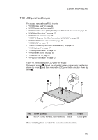
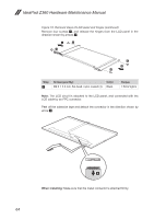
Removal steps of LCD panel and hinges continued
 |
View all Lenovo IdeaPad Z360 manuals
Add to My Manuals
Save this manual to your list of manuals |
Page 68 highlights
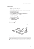
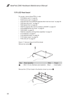
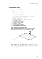
IdeaPad Z360 Hardware Maintenance Manual Figure 18. Removal steps of LCD panel and hinges (continued) Remove four screws 4, and release the hinges from the LCD panel in the direction shown by arrows 5. 5 4 4 4 5 4 Step 4 Screw (quantity) M2.0 × 3.0 mm, flat-head, nylon-coated (4) Color Black Torque 1.5±0.2 kgfcm Note: The LCD circuit is attached to the LCD panel, and connected with the LCD cable by an FPC connector. Peel off the adhesive tape and detach the connector in the direction shown by arrow 6. 6 When installing: Make sure that the metal connector is attached firmly. 64
-
 1
1 -
2
-
3
-
4
-
5
-
6
-
7
-
8
-
9
-
10
-
11
-
12
-
13
-
14
-
15
-
16
-
17
-
18
-
19
-
20
-
21
-
22
-
23
-
24
-
25
-
26
-
27
-
28
-
29
-
30
-
31
-
32
-
33
-
34
-
35
-
36
-
37
-
38
-
39
-
40
-
41
-
42
-
43
-
44
-
45
-
46
-
47
-
48
-
49
-
50
-
51
-
52
-
53
-
54
-
55
-
56
-
57
-
58
-
59
-
60
-
61
-
62
-
 63
63 -
 64
64 -
 65
65 -
 66
66 -
 67
67 -
 68
68 -
 69
69 -
 70
70 -
 71
71 -
 72
72 -
 73
73 -
74
-
75
-
76
-
77
-
78
-
79
-
80
-
81
-
82
-
83
-
84
-
85
-
86
-
87
-
88
-
89
 |
 |
64
IdeaPad Z360 Hardware Maintenance Manual
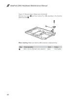
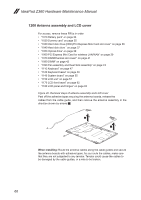
Figure 18. Removal steps of LCD panel and hinges (continued)
Remove
four screws
4
, and release the hinges from the LCD panel in the
direction shown by arrows
5
.
4
4
5
5
4
4
Step
Screw (quantity)
Color
Torque
4
M2.0 × 3.0 mm, flat-head, nylon-coated (4)
Black
1.5±0.2 kgfcm
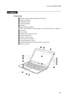
Note:
The LCD circuit is attached to the LCD panel, and connected with the
LCD cable by an FPC connector.
Peel off the adhesive tape and detach the connector in the direction shown by
arrow
6
.
6
When installing:
Make sure that the metal connector is attached firmly.