Lenovo IdeaPad Z360 Lenovo IdeaPad Z360 Hardware Maintenance Manual - Page 57
Speakers, power board and touch inductive panel
 |
View all Lenovo IdeaPad Z360 manuals
Add to My Manuals
Save this manual to your list of manuals |
Page 57 highlights
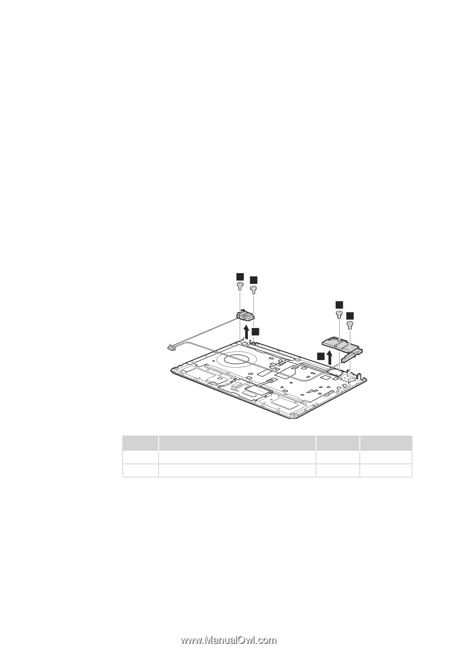
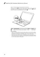
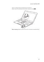
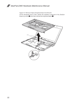
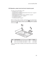
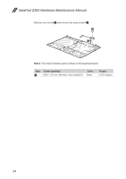
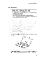
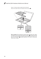
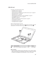
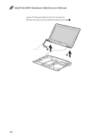
Lenovo IdeaPad Z360 1130 Speakers, power board and touch inductive panel For access, remove these FRUs in order: •• "1010 Battery pack" on page 34 •• "1030 Hard disk drive (HDD)/PCI Express Mini Card slot cover" on page 36 •• "1050 Optical drive" on page 38 •• "1060 PCI Express Mini Card for wireless LAN/WAN" on page 39 •• "1070 DIMM/thermal slot coverr" on page 41 •• "1110 Keyboard" on page 47 •• "1120 Keyboard bezel" on page 49 Figure 13. Removal steps of speakers, power board and touch inductive panel Turn over the keyboard bezel, remove four screws 1 2, release the speaker cables from the cable guides, and then remove the speakers in the direction shown by arrows 3. 11 2 1 3 3 Step 1 2 Screw (quantity) M2.0 × 3.5 mm, flat-head, nylon-coated (3) M2.0 × 5.0 mm, flat-head, nylon-coated (1) Color White White Torque 1.5±0.2 kgfcm 2.0±0.2 kgfcm Figure 13. Removal steps of speakers, power board and touch inductive panel (continued) 53
-
 1
1 -
2
-
3
-
4
-
5
-
6
-
7
-
8
-
9
-
10
-
11
-
12
-
13
-
14
-
15
-
16
-
17
-
18
-
19
-
20
-
21
-
22
-
23
-
24
-
25
-
26
-
27
-
28
-
29
-
30
-
31
-
32
-
33
-
34
-
35
-
36
-
37
-
38
-
39
-
40
-
41
-
42
-
43
-
44
-
45
-
46
-
47
-
48
-
49
-
50
-
51
-
 52
52 -
 53
53 -
 54
54 -
 55
55 -
 56
56 -
 57
57 -
 58
58 -
 59
59 -
 60
60 -
 61
61 -
 62
62 -
63
-
64
-
65
-
66
-
67
-
68
-
69
-
70
-
71
-
72
-
73
-
74
-
75
-
76
-
77
-
78
-
79
-
80
-
81
-
82
-
83
-
84
-
85
-
86
-
87
-
88
-
89
 |
 |