Lenovo IdeaPad Z360 Lenovo IdeaPad Z360 Hardware Maintenance Manual - Page 54
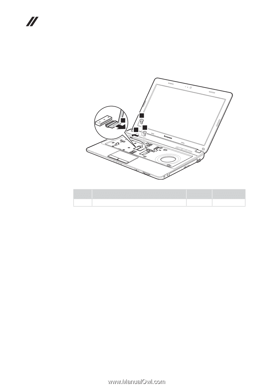
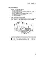
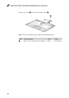
Screw quantity, Color, Torque, Removal steps of keyboard bezel continued
 |
View all Lenovo IdeaPad Z360 manuals
Add to My Manuals
Save this manual to your list of manuals |
Page 54 highlights
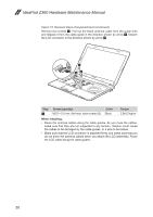
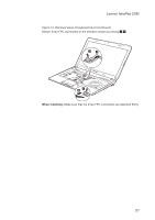
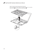
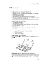
IdeaPad Z360 Hardware Maintenance Manual Figure 12. Removal steps of keyboard bezel (continued) Remove two screws 4. Pull out the black antenna cable form the guide hole and release it from the cable guide in the direction shown by arrow 5. Detach the LCD connector in the direction shown by arrow 6. 4 6 54 Step 4 Screw (quantity) M2.5 × 5.0 mm, flat-head, nylon-coated (2) Color Black Torque 2.5±0.2 kgfcm When installing: •• Route the antenna cables along the cable guides. As you route the cables, make sure that they are not subjected to any tension. Tension could cause the cables to be damaged by the cable guides, or a wire to be broken. •• Make sure that the LCD connector is attached firmly and make sure that you do not pinch the antenna cables when you attach the LCD assemblly. Route the LCD cable along the cable guides. 50
-
 1
1 -
2
-
3
-
4
-
5
-
6
-
7
-
8
-
9
-
10
-
11
-
12
-
13
-
14
-
15
-
16
-
17
-
18
-
19
-
20
-
21
-
22
-
23
-
24
-
25
-
26
-
27
-
28
-
29
-
30
-
31
-
32
-
33
-
34
-
35
-
36
-
37
-
38
-
39
-
40
-
41
-
42
-
43
-
44
-
45
-
46
-
47
-
48
-
 49
49 -
 50
50 -
 51
51 -
 52
52 -
 53
53 -
 54
54 -
 55
55 -
 56
56 -
 57
57 -
 58
58 -
 59
59 -
60
-
61
-
62
-
63
-
64
-
65
-
66
-
67
-
68
-
69
-
70
-
71
-
72
-
73
-
74
-
75
-
76
-
77
-
78
-
79
-
80
-
81
-
82
-
83
-
84
-
85
-
86
-
87
-
88
-
89
 |
 |