Lenovo ThinkPad X200s Hardware Maintenance Manual - Page 85
Table 12. Removal steps of keyboard continued, keyboard firmly in place.
 |
View all Lenovo ThinkPad X200s manuals
Add to My Manuals
Save this manual to your list of manuals |
Page 85 highlights
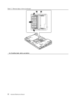
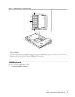
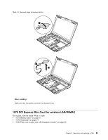
Table 12. Removal steps of keyboard (continued) Lift the keyboard a little in the direction shown by arrow 4 , and then detach the connector 5 . When installing: 1. Attach the keyboard connector firmly. 2. Make sure that the keyboard edges are under the frame as shown in this figure. Then press the keys to latch the keyboard firmly in place. 3. To make sure that the front side of the keyboard is housed firmly, gently press the keys with your thumbs and try to slide the keyboard toward you. Chapter 8. Removing and replacing a FRU 79
-
 1
1 -
2
-
3
-
4
-
5
-
6
-
7
-
8
-
9
-
10
-
11
-
12
-
13
-
14
-
15
-
16
-
17
-
18
-
19
-
20
-
21
-
22
-
23
-
24
-
25
-
26
-
27
-
28
-
29
-
30
-
31
-
32
-
33
-
34
-
35
-
36
-
37
-
38
-
39
-
40
-
41
-
42
-
43
-
44
-
45
-
46
-
47
-
48
-
49
-
50
-
51
-
52
-
53
-
54
-
55
-
56
-
57
-
58
-
59
-
60
-
61
-
62
-
63
-
64
-
65
-
66
-
67
-
68
-
69
-
70
-
71
-
72
-
73
-
74
-
75
-
76
-
77
-
78
-
79
-
 80
80 -
 81
81 -
 82
82 -
 83
83 -
 84
84 -
 85
85 -
 86
86 -
 87
87 -
 88
88 -
 89
89 -
 90
90 -
91
-
92
-
93
-
94
-
95
-
96
-
97
-
98
-
99
-
100
-
101
-
102
-
103
-
104
-
105
-
106
-
107
-
108
-
109
-
110
-
111
-
112
-
113
-
114
-
115
-
116
-
117
-
118
-
119
-
120
-
121
-
122
-
123
-
124
-
125
-
126
-
127
-
128
-
129
-
130
-
131
-
132
-
133
-
134
-
135
-
136
-
137
-
138
-
139
-
140
-
141
-
142
-
143
-
144
-
145
-
146
-
147
-
148
-
149
-
150
-
151
-
152
-
153
-
154
-
155
-
156
-
157
-
158
-
159
-
160
-
161
-
162
-
163
-
164
-
165
-
166
-
167
-
168
-
169
-
170
-
171
-
172
-
173
-
174
-
175
-
176
-
177
-
178
-
179
-
180
-
181
-
182
-
183
-
184
-
185
-
186
-
187
-
188
-
189
-
190
-
191
-
192
-
193
-
194
-
195
-
196
-
197
-
198
-
199
-
200
-
201
-
202
-
203
-
204
-
205
-
206
-
207
-
208
-
209
-
210
-
211
-
212
-
213
-
214
-
215
-
216
-
217
-
218
-
219
-
220
-
221
-
222
-
223
-
224
-
225
-
226
-
227
-
228
-
229
-
230
-
231
-
232
-
233
-
234
-
235
-
236
-
237
-
238
-
239
-
240
-
241
-
242
-
243
-
244
-
245
-
246
-
247
-
248
-
249
-
250
-
251
-
252
-
253
-
254
-
255
-
256
-
257
-
258
-
259
-
260
-
261
-
262
-
263
-
264
-
265
-
266
-
267
-
268
-
269
-
270
-
271
-
272
-
273
-
274
-
275
-
276
-
277
-
278
 |
 |

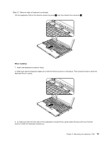
Table 12. Removal steps of keyboard (continued)
Lift the keyboard a little in the direction shown by arrow
4
, and then detach the connector
5
.
When installing:
1. Attach the keyboard connector firmly.
2. Make sure that the keyboard edges are under the frame as shown in this figure. Then press the keys to latch the
keyboard firmly in place.
3. To make sure that the front side of the keyboard is housed firmly, gently press the keys with your thumbs
and try to slide the keyboard toward you.
Chapter 8
.
Removing and replacing a FRU
79