LiftMaster SL585UL Installation Manual
LiftMaster SL585UL Manual
 |
View all LiftMaster SL585UL manuals
Add to My Manuals
Save this manual to your list of manuals |
LiftMaster SL585UL manual content summary:
- LiftMaster SL585UL | Installation Manual - Page 1
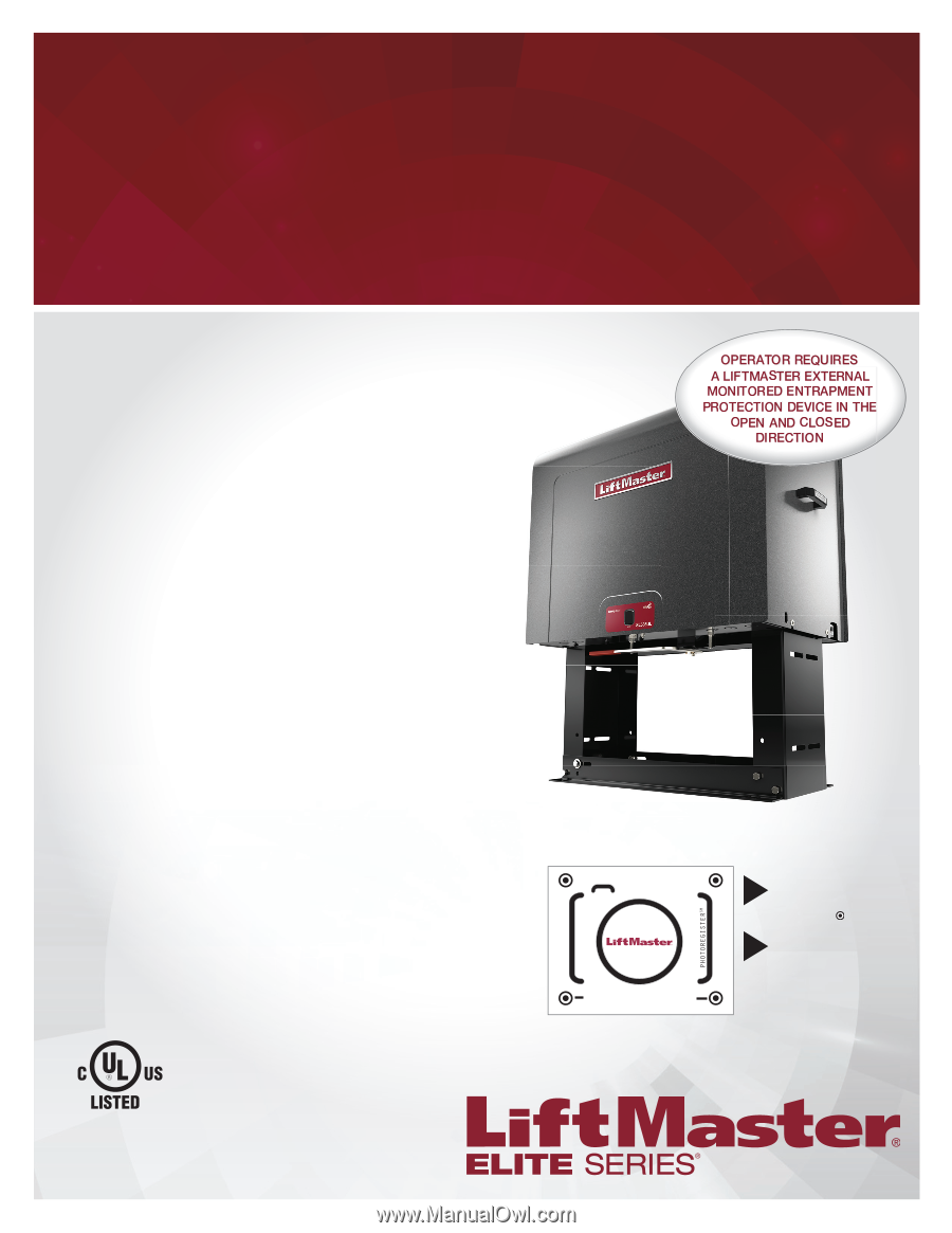
Model SL585UL ELITE SERIES INDUSTRIAL AC SLIDE GATE OPERATOR INSTALLATION MANUAL SL585101UL 1 HP, 120/208-240 Vac Single support guides or register this product 1. Take a photo of the camera icon including the points ( ). 2. Send it in by texting the photo to 71403. SL585ULTECH LiftMaster - LiftMaster SL585UL | Installation Manual - Page 2
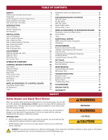
Dual Gate Settings 38 MAINTENANCE 39 Important Safety Instructions 39 Maintenance Chart 39 TROUBLESHOOTING 40 Diagnostic Codes 40 Diagnostic Codes Table 41 Operator Alarm 43 Troubleshooting Chart 44 ACCESSORIES 46 REPAIR PARTS 47 WARRANTY 48 SAFETY Safety Symbol and Signal - LiftMaster SL585UL | Installation Manual - Page 3
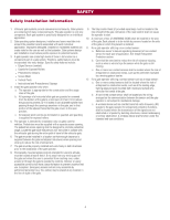
devices. IMPORTANT SAFETY INSTRUCTIONS To reduce the risk of INJURY or DEATH: l READ AND FOLLOW ALL INSTRUCTIONS. l NEVER let children not moving. l KEEP GATES PROPERLY MAINTAINED. Read the owner's manual. Have a qualified service person make repairs to gate hardware. l The entrance is for - LiftMaster SL585UL | Installation Manual - Page 4
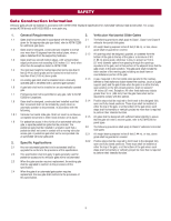
in the are comprised of many component parts. The gate operator is only one line sensor: a. Reference owner's manual regarding placement of non-contact . l Vertical Posts l Instructional and Precautionary Signage 4. Install A hard wired contact sensor shall be located and its wiring arranged so - LiftMaster SL585UL | Installation Manual - Page 5
wire shall not be less than 6 feet (1.83 m) above grade. An existing gate latch shall be disabled when a manually fixed stationary object nearest the roadway, (such as a gate support post) and the gate frame when the gate is in that the gate will enter a receiver guide, refer to ASTM F2200 for panel - LiftMaster SL585UL | Installation Manual - Page 6
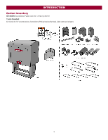
INTRODUCTION Carton Inventory NOT SHOWN: Documentation Packet, Chain #50 - 25 feet, Eye Bolt Kit Tools Needed 3/4" wrench for 1/2" concrete anchors, Screwdrivers (Phillips head and flat head), Cable cutters and strippers 6 - LiftMaster SL585UL | Installation Manual - Page 7
) protection device. Expansion board - up to 3 entrapment protection devices configurable to either close or open and up to 4 edge sensors using wireless edge sensor kit model LMWEKITU . 7 - LiftMaster SL585UL | Installation Manual - Page 8
20 Amps (26 Amps including Accessory Outlets) 10 Amps Accessory Outlets are rated for 120 Vac, 6 Amps maximum. NOTE: The outlet is only available on models with 120 Vac input. The 120 Vac outlet is automatically disabled when the operator is configured for any voltage other then 120 Vac. For 240 - LiftMaster SL585UL | Installation Manual - Page 9
INTRODUCTION Site Preparation Check the national and local building codes BEFORE installation. Conduit and Concrete Pad Trench and install conduit. Before trenching, contact underground utility locating companies. Conduit must be UL approved for low and high voltage. Consider the operator - LiftMaster SL585UL | Installation Manual - Page 10
INSTALLATION l To AVOID damaging gas, power or other underground utility lines, l To prevent damage to the operator or gate, DO NOT drive the limit contact underground utility locating companies BEFORE digging more (nuts) actuators on the shaft past their normal positions. than 18 inches (46 cm) - LiftMaster SL585UL | Installation Manual - Page 11
INSTALLATION Step 1 Install the Operator Check the national and local building codes before installation. Pad mount installation Retro-fit installation The operator is shipped from the factory with the lower mounting angles configured out (Figure 1). If you have pad constrictions, either angle can - LiftMaster SL585UL | Installation Manual - Page 12
INSTALLATION Post mount installation Retro-fit installation The operators come from the factory configured to mount to an inside the frame post mount dimension of 26" (66 cm) (outside to outside of posts). The frame comes slotted to accommodate posts 24-1/8" (61 cm) to 26" (66 cm), outside to - LiftMaster SL585UL | Installation Manual - Page 13
instructed. 1. Mount gate brackets to the vertical front and rear posts of the gate. 2. Remove the operator cover. 3. Locate and engage the manual through the plastic chain guide, around drive and idler sprockets, and then through the second plastic chain guide toward front gate bracket. support. 13 - LiftMaster SL585UL | Installation Manual - Page 14
Safety Guide l LiftMaster monitored external entrapment protection devices MUST be used with LiftMaster operators to meet UL325 requirements, see Accessories. l Test ALL entrapment protection devices after completing installation of the operator. For testing instructions, refer to the manual - LiftMaster SL585UL | Installation Manual - Page 15
Protection Devices There are three options for wiring the entrapment protection devices depending on the specific device and how the device will function. Refer to the specific entrapment protection device manual for more information. These entrapment protection device inputs are for monitored - LiftMaster SL585UL | Installation Manual - Page 16
) and locking-out the power via the operator power consulting the wiring diagram. switch. Upon completion of maintenance the area MUST be cleared and secured, at that time the unit may be returned to service. l ALL power wiring should be on a dedicated circuit and well protected. The location of - LiftMaster SL585UL | Installation Manual - Page 17
on the power board and plug the harness in to the "208V / 240V" receptacle. Swap the orange and red transformer wires (the red wire connects to the 240V position and the orange wire connects to the 208V position). Unplug the motor harness from the "120V" receptacle on the power board and plug the - LiftMaster SL585UL | Installation Manual - Page 18
harness is plugged in to the "208V / 240V" receptacle on the power board. Swap the orange and red transformer wires (the red wire connects to the 240V position and the orange wire connects to the 208V position). Unplug the motor power harness from the"208V / 240V" receptacle on the power board and - LiftMaster SL585UL | Installation Manual - Page 19
INSTALLATION Step 6 Dual Gate Setup There are two options for dual gate communication: wired or wireless. Follow the directions according to your application. Do not use wired and wireless communication simultaneously. Wireless setup To activate the wireless feature: 1. Choose an operator to be the - LiftMaster SL585UL | Installation Manual - Page 20
must be rated at 30 Volt minimum 1. Disconnect ALL power to the operator. 2. Trench across driveway to bury the shielded twisted pair cable. 3. Connect the wires from the shielded twisted pair cable to the Com Link terminals on the primary gate operator control board. NOTE: We recommend that all - LiftMaster SL585UL | Installation Manual - Page 21
ADJUSTMENT Adjust the Handing and Limits To reduce the risk of SEVERE INJURY or DEATH: l Without a properly installed safety reversal system, persons (particularly small children) could be SERIOUSLY INJURED or KILLED by a moving gate. l Too much force on gate will interfere with proper operation of - LiftMaster SL585UL | Installation Manual - Page 22
ADJUSTMENT Readjust the Limits To readjust the limits, follow the "Set the Limits" and "Set the Force and Run Distance" instructions above. It is important that the force and run distance are set after every limit readjustment. Adjust the Clutch The friction clutch system is not - LiftMaster SL585UL | Installation Manual - Page 23
ADJUSTMENT Fine Tune the Force Once the initial limits have been set, the REVERSAL FORCE DIAL on the control board is used for fine tuning the force where wind or environmental changes may affect the gate travel. The REVERSAL FORCE DIAL is set to minimum at the factory. Based on the length and - LiftMaster SL585UL | Installation Manual - Page 24
OPERATOR OVERVIEW 24 - LiftMaster SL585UL | Installation Manual - Page 25
CONTROL BOARD OVERVIEW 25 - LiftMaster SL585UL | Installation Manual - Page 26
display as "SL" followed by a "58" which indicates the operator type as SL585UL. The firmware version will show after the operator type, example "1.2". For more information about the codes refer to the Troubleshooting section. Handing Buttons The handing buttons are used to determine which direction - LiftMaster SL585UL | Installation Manual - Page 27
wear or temperature changes Test Buttons Used to operate the gate (OPEN, STOP and CLOSE). Also used to view the code history (refer to the Troubleshooting section). Status LEDs LED INPUT POWER TIMER GATE MOVING ACC PWR OVLD STATE OFF ON OFF ON 1 blink/second 2 blinks/second 8 blinks/second OFF ON - LiftMaster SL585UL | Installation Manual - Page 28
does not reset alarm condition). Used for exit probe, telephone entry, external exit loop detector, or any device that would command the gate to open. WIRING EXAMPLE SHADOW and COM l Opens a closing gate and holds open an open gate, if maintained, pauses Timer-to-Close at OPEN limit. This input - LiftMaster SL585UL | Installation Manual - Page 29
WIRE ACCESSORIES TO CONTROL BOARD Photoelectric Sensors and Edge Sensors The EYES/EDGE will reverse for 4 seconds then stop. This input will be disregarded during gate closing. WIRING EXAMPLE Locks TERMINALS NC and COM FUNCTION Normally Closed (N.C.) output for maglocks. Relay activates prior - LiftMaster SL585UL | Installation Manual - Page 30
LOOPDETLM) detects a fault, then the gate will open and remain open until fault is cleared. CLOSE: If the EXIT plug-in loop detector (model LOOPDETLM) detects a fault, faults are ignored (EXIT loop is faulted and inoperative). AC FAIL Switch NOT USED ANTI TAIL Switch OFF: When CLOSE EYES/Interrupt - LiftMaster SL585UL | Installation Manual - Page 31
used. Energizes if gate is manually tampered with by being pushed between 1,000 and 9,999,000 cycles. After servicing, set Aux Relay switches back to their appropriate positions Auxiliary relay wiring example RED/GREEN LIGHT FUNCTIONALITY Red light wired to AUX RELAY 1. Green light wired to AUX - LiftMaster SL585UL | Installation Manual - Page 32
EYE ONLY and COM Open or Close Direction Photoelectric Sensors, the functionality is based on the switch settings (located next to the terminals) WIRING EXAMPLE Switch set to CLOSE: gate reverses fully when an obstruction is sensed Switch set to OPEN: gate reverses 4 seconds when an obstruction - LiftMaster SL585UL | Installation Manual - Page 33
limit l Opens a closing gate and holds open an open gate Loop wire connection for plug-in loop detector when loop is positioned under the gate. l Disregarded during gate motion l Pauses Timer-to-Close at Open Limit Loop wire connection for plug-in loop detector when loop is on the outside of the - LiftMaster SL585UL | Installation Manual - Page 34
ADDITIONAL WIRING To protect against fire and electrocution: l DISCONNECT power (AC or solar and battery) BEFORE installing or servicing operator. For continued protection against fire: l Replace ONLY with fuse of same type and rating. Field Wiring 34 - LiftMaster SL585UL | Installation Manual - Page 35
to comply with the limits for a Class B digital device, pursuant to part 15 of the FCC rules and Industry Canada ICES standard. These limits are energy and, if not installed and used in accordance with the instructions, may cause harmful interference to radio communications. However, there is - LiftMaster SL585UL | Installation Manual - Page 36
ONE gate operator (see the KPW5/KPW250 manual for complete programming instructions). The Constant Pressure Override feature is intended present. External entrapment protection devices include LiftMaster monitored photoelectric sensors and LiftMaster monitored wired and wireless edge sensors. Be - LiftMaster SL585UL | Installation Manual - Page 37
alert system) to indicate if gate is manually tampered with by being pushed off of close limit. Cycle Quantity Feedback Use during servicing only to determine operator cycles. Use during servicing only to determine operator cycles. Use during servicing only to determine operator cycles. Use - LiftMaster SL585UL | Installation Manual - Page 38
Delay: ON (will open last and close first) Tandem Mode: OFF SECONDARY OPERATOR OFF Bi-Part Delay: OFF (will open first and close last) Tandem Mode: OFF ACCESSORY Remote Controls LiftMaster Internet Gateway Garage and Gate Monitor PRIMARY OPERATOR Program remote controls 1 to 50 to the primary - LiftMaster SL585UL | Installation Manual - Page 39
manual. national and local electrical codes. NOTE: The operator should be on Have a qualified service person make repairs to gate hardware. a separate fused line of adequate capacity. l ALL maintenance MUST be performed by a LiftMaster INSTRUCTIONS. operation Inspect all wire connections Check for - LiftMaster SL585UL | Installation Manual - Page 40
TROUBLESHOOTING To protect against fire and electrocution: l DISCONNECT power (AC or solar and battery) BEFORE installing or servicing operator. For continued protection against fire: l Replace ONLY with fuse of same type and rating. Diagnostic Codes To View the Codes The codes will show - LiftMaster SL585UL | Installation Manual - Page 41
TROUBLESHOOTING Diagnostic Codes Table Some codes are saved in the code history and some are not. If a code is not saved it will briefly appear on the display as it occurs, then disappear. LiftMaster or OPEN - LiftMaster Plug-in Loop Detector only) Check loop wiring throughout connection. May - LiftMaster SL585UL | Installation Manual - Page 42
TROUBLESHOOTING Code 70 71 72 73 74 75 80 81 82 wired bus or radio. Ensure operator is powered. May have to erase the wireless communication and reprogram the two operators. Check the connections between the main board and the expansion board. Non-monitored contact closure devices are not supported - LiftMaster SL585UL | Installation Manual - Page 43
TROUBLESHOOTING Operator Alarm If a contact sensor detects an obstruction twice consecutively the alarm will sound (up to 5 minutes) and the operator will need to be reset. - LiftMaster SL585UL | Installation Manual - Page 44
TROUBLESHOOTING Troubleshooting fully close when setting limits. Operator does not respond to a wired control/command (example: Open, Close, SBC, etc.) Operator does between the OPEN limit and the CLOSE limit. a. Use manual disconnect, manually move gate, and ensure gate moves easily limit to limit. - LiftMaster SL585UL | Installation Manual - Page 45
TROUBLESHOOTING SYMPTOM Shadow loop does not keep gate at open limit. Obstruction in terminals). If shorting lock's NO and COM wires does not activate Maglock, then replace Maglock or Maglock wiring (refer to Wiring Diagrams). a. Check that Solenoid is wired to N.O. and COM terminals. Check that - LiftMaster SL585UL | Installation Manual - Page 46
Plug-in loop detector Model LOOPDETLM LiftMaster door and gate monitor 3-button control station Model 829LM Model 02-103 Stop Button Model AEXITP Warning sign Model 40-39235 LiftMaster elite series maglock package Model MG1300RLYPKG Heater kit accessory Model HTRNB Model HTR460 for 460V - LiftMaster SL585UL | Installation Manual - Page 47
REPAIR PARTS REPAIR PARTS (NOT SHOWN) Heater Kit, 480V Feather Key Chain Guard Kit Complete with: Chain guard, chain guides and retainers 39304 65-3506 K10-3209 K11-3503 K19-3025 K77-37683 65-3509 ELECTRICAL BOX REPAIR PARTS (NOT SHOWN) Power Board Horse Power ID, 3 Phase 1/2 HP K94-38062-1 Power - LiftMaster SL585UL | Installation Manual - Page 48
service center for warranty repair. You will be advised of shipping instructions when you call. Please include a brief description of the problem Defective parts will be repaired or replaced with new or factoryrebuilt parts at LiftMaster.com © 2018, The Chamberlain Group, Inc. - All Rights Reserved
-
 1
1 -
 2
2 -
 3
3 -
 4
4 -
 5
5 -
 6
6 -
 7
7 -
8
-
9
-
10
-
11
-
12
-
13
-
14
-
15
-
16
-
17
-
18
-
19
-
20
-
21
-
22
-
23
-
24
-
25
-
26
-
27
-
28
-
29
-
30
-
31
-
32
-
33
-
34
-
35
-
36
-
37
-
38
-
39
-
40
-
41
-
42
-
43
-
44
-
45
-
46
-
47
-
48
 |
 |
ELITE SERIES INDUSTRIAL
AC SLIDE GATE OPERATOR
Model
SL585UL
INSTALLATION MANUAL
LiftMaster
300 Windsor Drive
Oak Brook, IL 60523
•
THIS PRODUCT IS TO BE INSTALLED AND
SERVICED BY A TRAINED GATE SYSTEMS
TECHNICIAN ONLY.
•
This model is for use on vehicular passage gates
ONLY and not intended for use on pedestrian
passage gates.
•
This model is intended for use in Class I, II, III and
IV vehicular slide gate applications.
•
Visit LiftMaster.com to locate a professional
installing dealer in your area.
•
This gate operator is compatible with MyQ
®
and
Security+ 2.0
®
accessories.
SL585101UL
1 HP, 120/208-240 Vac Single Phase
SL585103UL
1 HP, 208-240/480 Vac Three Phase
SL585105UL
1 HP, 575 Vac Three Phase
SL585151UL
1-1/2 HP, 120/208-240 Vac Single Phase
SL585501UL
1/2 HP, 120/208-240 Vac Single Phase
SL585503UL
1/2 HP, 208-240/480 Vac Three Phase
SL585505UL
1/2 HP, 575 Vac Three Phase
Access installation and technical support
guides or register this product
Send it in
by texting the
photo to 71403.
Take a photo
of the
camera icon including
the points (
).
1.
2.
SL585ULTECH