LiftMaster SL585UL Installation Manual - Page 20
Wired Setup, Dual Gate Wire Type Shielded Twisted Pair Cable
 |
View all LiftMaster SL585UL manuals
Add to My Manuals
Save this manual to your list of manuals |
Page 20 highlights
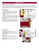
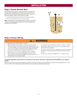
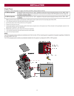
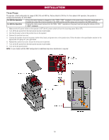
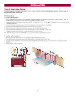
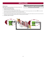
INSTALLATION Wired setup Before digging, contact local underground utility locating companies. Use PVC conduit to prevent damage to cables. DUAL GATE WIRE TYPE (SHIELDED TWISTED PAIR CABLE) 22AWG up to 200 feet (61 m) 18AWG - 200-1000 feet (61-305 m) Wire must be rated at 30 Volt minimum 1. Disconnect ALL power to the operator. 2. Trench across driveway to bury the shielded twisted pair cable. 3. Connect the wires from the shielded twisted pair cable to the Com Link terminals on the primary gate operator control board. NOTE: We recommend that all accessories and board configurations are set on the primary operator. 4. Route the shielded twisted pair cable to the secondary gate operator's control board. 5. Connect the wires from the shielded twisted pair cable to the Com Link terminals on the secondary control board (Com Link A to Com Link A and Com Link B to Com Link B). Ground the shield of the cable to the chassis ground of one operator. 6. Connect ALL power to the operator. 20
-
 1
1 -
2
-
3
-
4
-
5
-
6
-
7
-
8
-
9
-
10
-
11
-
12
-
13
-
14
-
 15
15 -
 16
16 -
 17
17 -
 18
18 -
 19
19 -
 20
20 -
 21
21 -
 22
22 -
 23
23 -
 24
24 -
 25
25 -
26
-
27
-
28
-
29
-
30
-
31
-
32
-
33
-
34
-
35
-
36
-
37
-
38
-
39
-
40
-
41
-
42
-
43
-
44
-
45
-
46
-
47
-
48
 |
 |
