Linksys SGE2000 Cisco RPS1000 380W Redundant Power Supply Administration Guide - Page 11
Deployment Strategies
 |
UPC - 745883572120
View all Linksys SGE2000 manuals
Add to My Manuals
Save this manual to your list of manuals |
Page 11 highlights
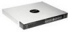
Chapter RPS1000-Business Series 380W RPS Unit Installation & Administration 2 16-pin connector plugs into the RPS1000, and the 14-pin connector plugs into the device. Use only the Cisco cable for this connection. WARNING: Attach only the RPS1000 cable (part # RPSCBL1) to the RPS1000 receptacle. Deployment Strategies You can deploy the RPS1000 in a variety of situations with mission-critical applications. One application might be in a voice and data network in which Linksys Business Series switches are connected to Linksys Business Series IP phones and PCs. Connecting an RPS1000 to the switches can prevent voice network failures that are caused by switch failures. Another application might be that of using traditional data 10/100/1000 Ethernet switches that carry mission-critical data. These applications would typically use one RPS1000 to support one to six switches as shown below. Ethernet Switches 181531 DC output 6 RPS 1000 DC output 1 In this configuration, if one device has a power-supply or power-related failure, the RPS1000 immediately begins to supply power to this device and is no longer available as a backup power source for the other devices. The RPS1000 sends status information to network management software to alert the system administrator that the other devices are not supported until the failed device or the power supply in the failed device is repaired or replaced. Chapter 2: Product Overview 8 Deployment Strategies
-
 1
1 -
2
-
3
-
4
-
5
-
 6
6 -
 7
7 -
 8
8 -
 9
9 -
 10
10 -
 11
11 -
 12
12 -
 13
13 -
 14
14 -
 15
15 -
 16
16 -
17
-
18
-
19
-
20
-
21
-
22
-
23
-
24
-
25
-
26
-
27
-
28
-
29
-
30
 |
 |
