Linksys SGE2000 Cisco RPS1000 380W Redundant Power Supply Administration Guide - Page 21
STBY/ACTIVE LED does not blink amber, see B, Troubleshooting.
 |
UPC - 745883572120
View all Linksys SGE2000 manuals
Add to My Manuals
Save this manual to your list of manuals |
Page 21 highlights
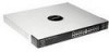
Chapter RPS1000-Business Series 380W RPS Unit Installation & Administration 3 NOTE: The switch might restart when it changes from RPS1000 power to its own internal power. This situation might occur after the power supply on a switch fails, the RPS1000 takes over, and the switch reverts to its own power. We advise you to assume this possibility and plan accordingly when you restart a switch using its internal power after using the RPS1000 as backup power. WARNING: Before working on a system that has an on/ off switch, turn OFF the power and unplug the power cord. With the RPS1000 on a desktop or in a rack, connect devices as follows: 1. If the RPS1000 is already connected to AC power, press the STBY/ACTIVE button on the RPS1000 to put it into standby mode or disconnect the RPS1000 from the AC power. If you pressed the STBY/ACTIVE button, the STBY/ACTIVE LED should begin blinking amber. If the STBY/ACTIVE LED does not blink amber, see Chapter B, "Troubleshooting". 2. Connect one end of an RPS1000 connector cable (part number: RPSCBL1) to an RPS1000 DC output connector. To ensure proper operation, be sure that you completely seat the connector and that you securely tighten the screw. NOTE: The connector is designed to be inserted into the receptacle in its correct orientation. WARNING: Attach only the Cisco RPS1000 (model PWR675-AC-RPS-N1) to the RPS1000 receptacle. 3. Connect the other end of the RPS1000 connector cable to the RPS1000 receptacle on the switch. 4. Repeat 2. through 3. for each switch that the RPS1000 will support. Chapter 3: Installation 18 Connecting the RPS1000
-
 1
1 -
2
-
3
-
4
-
5
-
6
-
7
-
8
-
9
-
10
-
11
-
12
-
13
-
14
-
15
-
 16
16 -
 17
17 -
 18
18 -
 19
19 -
 20
20 -
 21
21 -
 22
22 -
 23
23 -
 24
24 -
 25
25 -
 26
26 -
27
-
28
-
29
-
30
 |
 |
