MSI 945GM3-F User Guide - Page 30
Fan Power Connectors: CPUFAN1, SYSFAN1, PWRFAN1, Chassis Intrusion Switch Connector: JCI1 - cpu support
 |
UPC - 816909037449
View all MSI 945GM3-F manuals
Add to My Manuals
Save this manual to your list of manuals |
Page 30 highlights
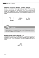
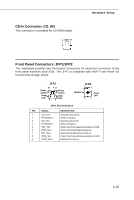
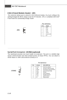
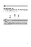
MS-7267 Mainboard Fan Power Connectors: CPUFAN1, SYSFAN1, PWRFAN1 The fan power connectors support system cooling fan with +12V. W hen connecting the wire to the connectors, always take note that the red wire is the positive and should be connected to the +12V, the black wire is Ground and should be connected to GND. If the mainboard has a System Hardware Monitor chipset on-board, you must use a specially designed fan with speed sensor to take advantage of the CPU fan c on tr ol . CONTROL SE NS OR +1 2V GND CPUFAN1 GND +12V SENSOR SYSFAN1 GND +12V SENSOR PWRFAN1 Important Please refer to the recommended CPU fans at Intel® official website or consult the vendors for proper CPU cooling fan. Chassis Intrusion Switch Connector: JCI1 This connector connects to a 2-pin chassis switch. If the chassis is opened, the switch will be short. The system will record this status and show a warning message on the screen. To clear the warning, you must enter the BIOS utility and clear the record. JCI1 GND CINTRU 1 2-14
-
 1
1 -
2
-
3
-
4
-
5
-
6
-
7
-
8
-
9
-
10
-
11
-
12
-
13
-
14
-
15
-
16
-
17
-
18
-
19
-
20
-
21
-
22
-
23
-
24
-
 25
25 -
 26
26 -
 27
27 -
 28
28 -
 29
29 -
 30
30 -
 31
31 -
 32
32 -
 33
33 -
 34
34 -
 35
35 -
36
-
37
-
38
-
39
-
40
-
41
-
42
-
43
-
44
-
45
-
46
-
47
-
48
-
49
-
50
-
51
-
52
-
53
-
54
-
55
-
56
-
57
-
58
-
59
-
60
-
61
-
62
-
63
-
64
-
65
-
66
-
67
-
68
-
69
-
70
-
71
-
72
-
73
-
74
-
75
-
76
-
77
-
78
-
79
-
80
-
81
-
82
 |
 |
