MSI K9N SLI-F User Guide
MSI K9N SLI-F - Motherboard - ATX Manual
 |
UPC - 816909043235
View all MSI K9N SLI-F manuals
Add to My Manuals
Save this manual to your list of manuals |
MSI K9N SLI-F manual content summary:
- MSI K9N SLI-F | User Guide - Page 1
K9N SLI/ K9N Ultra Series MS-7250 (V2.X) Mainboard G52-72501XF i - MSI K9N SLI-F | User Guide - Page 2
, please try the following help resources for further guidance. Visit the MSI website for FAQ, technical guide, BIOS updates, driver updates, and other information: http://www.msi.com.tw/program/service/faq/ faq/esc_faq_list.php Contact our technical staff at: http://support.msi.com.tw/ ii - MSI K9N SLI-F | User Guide - Page 3
1. Always read the safety instructions carefully. 2. Keep this User's Manual for future reference. 3. Keep this . 11. If any of the following situations arises, get the equipment checked by a service personnel: † The power cord or plug is damaged. † Liquid has penetrated into the equipment - MSI K9N SLI-F | User Guide - Page 4
if not installed and used in accordance with the instructions, may cause harmful interference to radio communications. However, limits. VOIR LANOTICE D'INSTALLATIONAVANT DE RACCORDER AU RESEAU. Micro-Star International MS-7250 This device complies with Part 15 of the FCC Rules. Operation is subject - MSI K9N SLI-F | User Guide - Page 5
WEEE (Waste Electrical and Electronic Equipment) Statement v - MSI K9N SLI-F | User Guide - Page 6
vi - MSI K9N SLI-F | User Guide - Page 7
vii - MSI K9N SLI-F | User Guide - Page 8
Support ...ii Safety Instructions MSI Special feature 1-7 Chapter 2 Hardware Setup 2-1 Quick Components Guide 2-2 CPU (Central Processing Unit 2-3 CPU Installation Procedures for Socket AM2 2-4 Installing AMD Socket AM2 CPU Module Header: JIR1 2-15 Front USB Connectors: JUSB1, JUSB2 & JUSB3 - MSI K9N SLI-F | User Guide - Page 9
Chipset Features 3-11 Integrated Peripherals 3-12 Power Management Setup 3-15 PNP/PCI Configurations 3-18 H/W Monitor ...3-20 Cell Menu ...3-21 Load Fail-Safe/ Optimized Defaults 3-27 BIOS Setting Password 3-28 Appendix A Realtek ALC888 Audio A-1 Installing the Realtek HD Audio Driver - MSI K9N SLI-F | User Guide - Page 10
RAID Configurations B-2 RAID Configuration B-3 Basic Configuration Instructions B-3 Setting Up the NVRAID BIOS B-3 Installing the RAID Driver (for bootable RAID Array B-7 NVIDIA IDE Driver/ RAID Utility Installation B-9 Installing the NVIDIA RAID Software Under W indows (for Non-bootable RAID - MSI K9N SLI-F | User Guide - Page 11
Getting Started Chapter 1 Getting Started Thank you for choosing the K9N SLI/ K9N Ultra Series (MS-7250 v2.X) ATX mainboard. The K9N SLI/ K9N Ultra S eries mainboards are based on nVIDIA® nForce 570 SLI/ nForce 570 chipsets f or optimal system efficiency. Designed to fit the advanced AMD® Athlon 64 - MSI K9N SLI-F | User Guide - Page 12
AM2 package. (For the latest information about CPU, please visit http://www.msi. c om. t w / pr og ra m/ p r od u c t s / ma in b oar d / mb d/ p ro_ mb d _c p u _s u pp ort . php) Supported FSB - HyperTransport supporting speed up to 1GHz (2000MT/s) Chipset - nVIDIA® nForce 570 SLI for K9N SLI - MSI K9N SLI-F | User Guide - Page 13
4 USB 2.0 Ports. - 2 LAN jacks (10/100/1000) by Vitesse VSC8601 - 5 flexible audio jacks. - 1 Optical SPDIF-out jack. On-Board Pinheaders - 1 D-Bracket 2 pinheader - 1 IrDA pinheader - 3 USB 2.0 pinheaders - 1 IEEE 1394 pinheader (optional) Slots For K9N SLI Series - 2 PCI Express x 16 slots support - MSI K9N SLI-F | User Guide - Page 14
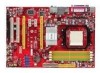
JIR 1 D I MM 3 D I MM 4 D I MM 1 D I MM 2 IDE1 PW R 1 n vi di a nForce 570 SLI SATA5 NBFAN1 SATA 6 S ATA1 S ATA2 S ATA3 S ATA4 VI A VT6307 ( op t io n a l ) J 1 3 94 _ 1 (optional ) JUS B2 JUSB 3 SW2 BIOS JUS B1 B AT T + JDB1 JFP2 JFP1 K9N SLI Series (MS-7250 v2.X) ATX Mainboard 1-4 - MSI K9N SLI-F | User Guide - Page 15
JIR 1 D I MM 3 D I MM 4 D I MM 1 D I MM 2 IDE1 PW R 1 nvidia nForce 570 SATA5 NBFAN1 S ATA 6 S ATA1 S ATA2 S ATA3 S ATA4 VIA VT6307 ( o pt i o na l ) J 13 9 4 _1 ( o pt i on a l ) JUSB2 JUSB3 SW2 BIOS JUSB1 B AT T + JDB1 JFP2 JFP1 K9N Ultra Series (MS-7250 v2.X) ATX Mainboard 1-5 - MSI K9N SLI-F | User Guide - Page 16
MS-7250 Mainboard Packing Checklist MSI motherboard MSI Driver/Utility CD Power Cable SATA Cable Standard Cable for IDE Devices (optional) Back IO Shield User's Guide SLI Video Link Card (for K9N SLI series only) * The pictures are for reference only and may vary from the packing contents - MSI K9N SLI-F | User Guide - Page 17
MSI Special Feature Core Center The Core Center is a new utility you can find in the CD-ROM disk. The utility is just like your PC doctor that can detect, view and adjust the PC hardware and system status during real time operation. Cool'n'Quiet This utility provides a CPU when the CPU temperature - MSI K9N SLI-F | User Guide - Page 18
MS-7250 menu, here you can configure the PC hardware status such as CPU & system temperatures and fan speeds. You may use the scroll activated and will be working properly, it is required to double confirm that: 1. Run BIOS Setup, and select Cell Menu. Under Cell Menu, find Cool'n'Quiet, and set this - MSI K9N SLI-F | User Guide - Page 19
Hardware Setup Chapter 2 Hardware Setup This chapter provides you with the information about hardware setup procedures. While doing the installation, be careful in holding the components and follow the installation procedures. For some components, if you install in the wrong orientation, the - MSI K9N SLI-F | User Guide - Page 20
MS-7250 Mainboard Quick Components Guide Back Panel I / O, p.2-10 PWR2, p.2-8 CPU, p.2-3 CPUFAN1, SYSFAN1, p.2-14 p.2-14 PWR3, p.2-8 DDRII DIMMs, p.2-6 JIR1, p.2-15 JCI1, p.2-14 FDD1, JDB1, p.2-19 JUSB1~3, p.2-16 J1394_1 (optional), p.2-17 * The picture above is for K9N SLI series. 2-2 - MSI K9N SLI-F | User Guide - Page 21
(Central Processing Unit) The mainboard supports AMD® Athlon64 X2/ Athlon64 & Athlon FX processors. The mainboard uses a CPU socket called Socket AM2 for easy CPU installation. W hen you are installing the CPU, make sure the CPU has a heat sink and a cooling fan attached on the top to prev ent ov - MSI K9N SLI-F | User Guide - Page 22
MS-7250 Mainboard CPU Installation Procedures for Socket AM2 1. Please turn off the power and unplug the power cord before installing the CPU. 2. Pull the lever sideways away from the socket. Make sure to raise the lever up to a 90-degree angle. Sliding Plate Open Lever 90 degree 3. - MSI K9N SLI-F | User Guide - Page 23
Hardware Setup Installing AMD Socket AM2 CPU Cooler Set W hen you are installing the CPU, make sure the CPU has a heat sink and a cooling shown in this section are for demonstration of the cooler installation for Socket AM2 CPUs only. The appearance of your mainboard may vary depending on the model - MSI K9N SLI-F | User Guide - Page 24
MS-7250 Mainboard Memory The mainboard provides four 240-pin non-ECC DDRII DIMMs and supports up to 8GB system memory. For more information on compatible components, please visit http://www.msi.com.tw/ p ro gr a m/ pr o du c t s /m ain bo ar d /m bd / pr o_ m bd _t r p_ lis t. ph p DDRII 240-pin, - MSI K9N SLI-F | User Guide - Page 25
ty in different channel DDR DIMMs. - To enable successful system boot-up, always insert the memory modules into the DIM M1 first. - Due to the chipset resource deployment, the system density will only be detected up to 7+GB (not full 8GB) when each DIMM is installed with an 2GB memory module. 2-7 - MSI K9N SLI-F | User Guide - Page 26
MS-7250 Mainboard Power Supply ATX 24-Pin Power Connector: PWR1 This connector allows you ATX 12V Power Connector: PWR3/ PWR2 This 12V power connector PW R3 is used to provide power to the CPU. This 12V power connector PW R2 is used to provide power to stable the operation of graphics card. PWR3 - MSI K9N SLI-F | User Guide - Page 27
Hardware Setup Important Notification about Power Issue NForce chipset is very sensitive to ESD (Electrostatic are very sensitive to ESD, so this kind of memory-replacement actions might cause system chipset unable to boot. Please follow the following solution to avoid this situation. Unplug the - MSI K9N SLI-F | User Guide - Page 28
MS-7250 Mainboard Back Panel Mouse Parallel Port LAN LAN L-In RS-Out Keyboard Serial Port 1394 S/PDIFPort Out (optional) USB Ports L-Out CS-Out Mic S/PDIFOut Mouse/Keyboard Connector The standard PS/2® mouse/keyboard DIN connector is for a PS/2® mouse/keyboard. Parallel Port Connector A - MSI K9N SLI-F | User Guide - Page 29
Serial Bus root is for attaching USB devices such as keyboard, mouse, or other USB-compatible devices. Audio Port Connectors These audio connectors are used on Vista operating system, you have to install the Realtek Audio Driver. Optical S/PDIF-Out connector This SPDIF (Sony & Philips Digital - MSI K9N SLI-F | User Guide - Page 30
MS-7250 Mainboard Connectors Floppy Disk Drive Connector: FDD1 This standard FDD connector supports 360K, 720K, 1.2M, 1. transfer rates between the computer and the hard drive up to 133 megabytes (MB) per second. The new interface is one-third faster than earlier record- setting instructions. 2-12 - MSI K9N SLI-F | User Guide - Page 31
Hardware Setup Serial ATA II Connectors: SATA1~SATA6 SATA1~SATA6 are high-speed SATAII interface ports. Each supports data rates of 300 MB/s and is fully compliant with Serial ATA specifications. Each Serial ATA connector can connect to 1 hard disk device. SATA5 SATA6 SATA1 SATA2 SATA3 SATA4 - MSI K9N SLI-F | User Guide - Page 32
MS-7250 Mainboard Fan Power Connectors: CPUFAN1, SYSFAN1 & NBFAN1 The fan power connectors support system cooling fan with + If the mainboard has a System Hardware Monitor chipset on-board, you must use a specially designed fan with speed sensor to take advantage of the CPU fan c on tr ol . GND +1 - MSI K9N SLI-F | User Guide - Page 33
the front panel audio and is compliant with Intel® Front Panel I/O Connectivity Design Guide. 2 1 10 9 JAUD1 PIN SIGNAL 1 MIC_L 2 GND 3 MIC_R Definition Audio CODEC jack detection resistor network No control Analog Port - Left channel Jack detection return from front panel JACK2 IrDA - MSI K9N SLI-F | User Guide - Page 34
MS-7250 Mainboard Front USB Connectors: JUSB1, JUSB2 & JUSB3 The mainboard provides USB 2.0 pinheaders (optional USB 2.0 bracket available) that are compliant with Intel® I/O Connectivity Design Guide. USB 2.0 technology increases data transfer rate up to a maximum throughput of 480Mbps, which is - MSI K9N SLI-F | User Guide - Page 35
Hardware Setup IEEE 1394 Connector: J1394_1 (optional) The mainboard provides IEEE1394 pinheader that allows you to connect IEEE 1394 ports via an external IEEE1394 bracket (optional). 9 1 10 2 J1394_1 Pin Definition PIN SIGNAL PIN 1 TPA+ 2 3 Ground 4 5 TPB+ 6 7 Cable power 8 9 - MSI K9N SLI-F | User Guide - Page 36
MS-7250 Mainboard Front Panel Connectors: JFP1/JFP2 The mainboard provides two front panel connectors for electrical connection to the front panel switches and LEDs. The JFP1 is compliant with Intel® Front Panel I/O Connectivity Design Guide. JFP1 10 Power Switch + Power LED 2 9 +Reset - Switch - MSI K9N SLI-F | User Guide - Page 37
2 is an external USB Bracket that supports both USB1.1 & 2.0 specs. It integrates four LEDs and allows users to identify system problems through 16 vari- CPU clock, 4 checking type ofvideo onboard. Then, detect and initializethe video adapter. 1 2 EarlyChipset Initialization 3 4 BIOS Sign - MSI K9N SLI-F | User Guide - Page 38
MS-7250 Mainboard Button The motherboard provides the following button for you to set the computer's function. This section will explain how to change your motherboard's function through the use of button. Clear CMOS Button: SW2 There is a CMOS RAM on board that has a power supply from external - MSI K9N SLI-F | User Guide - Page 39
GB/s over a PCI Express x16 lane for graphics controllers, while PCI Express x1 supports transfer rate of 250 MB/s. PCI Express x16 Slot PCI Express x1 Slot Important 1. When adding or removing card, such as jumpers, switches or BIOS configuration. 2. The K9N SLI Series support SLI technology. 2-21 - MSI K9N SLI-F | User Guide - Page 40
MS-7250 Mainboard NV SLI Technology (For K9N SLI Series only) NVIDIA SLI (Scalable Link Interface) technology allows two GPUs to run in tandem within a system to achieve up to twice the performance of a single graphics card. To utilize this technology, the two GPU cards must be connected by an SLI - MSI K9N SLI-F | User Guide - Page 41
driver/utility. A configuration panel will be provided for Multi-GPU control. Check the Enable multi-GPU box to enable the SLI function for the onboard graphics cards (concerning the details of multi-GPU settings, please refer to your graphics card manual) . Check the box 3. Restart your system and - MSI K9N SLI-F | User Guide - Page 42
MS-7250 Mainboard PCI (Peripheral Component Interconnect) Slots The PCI slots support LAN cards, SCSI cards, USB cards, and other add-on cards that comply with PCI specifications. At 32 bits and 33 MHz, it yields a throughput rate of 133 MBps. 32- - MSI K9N SLI-F | User Guide - Page 43
This chapter provides information on the BIOS Setup program and allows you to configure the system for optimum use. You may need to run the Setup program when: ² An error message appears - MSI K9N SLI-F | User Guide - Page 44
MS-7250 Mainboard Entering Setup Power on the computer and the system will start to BIOS maker as A = AMI, W = AWARD, and P = PHOENIX. 2nd - 5th digit refers to the model number. 6th digit refers to the chipset as I = Intel, N = nVidia, and V = VIA. 7th - 8th digit refers to the customer as MS = - MSI K9N SLI-F | User Guide - Page 45
BIOS Setup Control Keys Enter> Move to the sub-menu. If you want to return to the main menu, just press the . General Help The BIOS setup program provides a General Help screen. You can call up this screen from any menu by simply pressing . The - MSI K9N SLI-F | User Guide - Page 46
MS-7250 Mainboard The Main Menu Standard CMOS Features Use this menu for basic system configurations, such as time, date etc. Advanced BIOS Features Use this menu to setup the items of AMI® special enhanced features. Advanced Chipset Features Use this menu to change the values in the chipset - MSI K9N SLI-F | User Guide - Page 47
Use this menu to load the default values set by the mainboard manufacturer specifically for optimal performance of the mainboard. BIOS Setting Password Use this menu to set the password for BIOS. Save & Exit Setup Save changes to CMOS and exit setup. Exit Without Saving Abandon all changes and exit - MSI K9N SLI-F | User Guide - Page 48
MS-7250 Mainboard Standard CMOS Features The items in Standard CMOS Features Menu includes The format is . day Day of the week, from Sun to Sat, determined by BIOS. Read-only. month The month from Jan. through Dec. date The date from 1 to 31 can be keyed by numeric - MSI K9N SLI-F | User Guide - Page 49
BIOS Setup Device/ Vender/ Size/ LBA Mode/ Block M ode/ PIO Mode/ Async DM A/ Ultra M ode This allows you to enable or disable the LBA Mode. Setting to Auto enables LBA mode if the device supports it and the devices is not already formatted with LBA mode disabled. DM A M ode Select DMA Mode. Hard - MSI K9N SLI-F | User Guide - Page 50
MS-7250 Mainboard Halt On The setting determines whether the system will stop if Press to enter the sub-menu, and the following screen appears. Usage Memory/ BIOS Version/ CPU Information These items show the CPU information, BIOS version and memory status of your system (read only). 3-8 - MSI K9N SLI-F | User Guide - Page 51
the virus warning feature for IDE Hard Disk boot sector protection. If this function is enabled and someone attempt to write date into this area, BIOS will shows a warning message on screen and alarm beep. Boot To OS/2 This allows you to run the OS/2® operating system with DRAM larger than - MSI K9N SLI-F | User Guide - Page 52
MS-7250 Mainboard IOAPIC Function This field is used to enable or disable the APIC (Advanced Programmable Interrupt Controller). Due to compliance with PC2001 design guide, the system is able to run in APIC mode. Enabling APIC mode will expand available IRQ resources for the system. MPS Table - MSI K9N SLI-F | User Guide - Page 53
Advanced Chipset Features BIOS Setup Hyper Transport MCP55 Configuration MCP55 (SB) to AM 2 (CPU) Freq Auto [Enabled] Auto Detect HT frequency. [Disabled] Manual to setting HT frequency. M CP55 (SB) to AM 2 (CPU) Frequency W hen the MCP55 (SB) to AM2 (CPU) Freq Auto set to Disabled, the item - MSI K9N SLI-F | User Guide - Page 54
MS-7250 Mainboard Integrated Peripherals USB / 2.0 Controller This setting allows you to enable/disable the onboard USB 1.1/ 2.0 controller. USB Device Legacy Support Select [Enabled] if you need to use a USB-interfaced device in the operating system. Onboard Devices Configuration Press to - MSI K9N SLI-F | User Guide - Page 55
setting allows you to specify the operation mode for serial port. Settings are: [Disabled] RS-232C Serial Port [Enabled] IrDA-compliant Serial Infrared Port Parallel Port There is a built-in parallel port on the on-board Super I/O chipset that provides Standard, ECP, and EPP features. It has - MSI K9N SLI-F | User Guide - Page 56
MS-7250 Mainboard Parallel Port IRQ This item allows you to set parallel port IRQ. IDE Devices Configuration Press to enter the sub-menu and the following screen appears: PCI IDE BusMaster This item allows you to enable/ disable BIOS to used PCI busmastering for reading/ writing to IDE - MSI K9N SLI-F | User Guide - Page 57
functions described in this section are available only when your BIOS supports S3 sleep mode. ACPI Function This item is to S1 sleep mode is a low power state. In this state, no system context is lost (CPU or chipset) and hardware main- tains all system context. [S3/STR] The S3 sleep mode is a - MSI K9N SLI-F | User Guide - Page 58
MS-7250 Mainboard Power Button Function This feature sets the function of the power button. Event Setup Press and the following sub-menu appears. Resume From S3 by USB Device The item allows the activity of the USB device to wake up the system from S3 (Suspend to RAM) sleep state. Resume - MSI K9N SLI-F | User Guide - Page 59
BIOS Setup Resume by PCIE Device W hen set to [Enabled], the feature allows your system to be awakened from the power saving modes through any event on PCIE device. Resume by RTC Alarm The field is used to enable or disable the feature of booting up the system on a scheduled time/date. 3-17 - MSI K9N SLI-F | User Guide - Page 60
MS-7250 Mainboard PNP/PCI Configurations This section describes configuring the PCI bus system and PnP (Plug & Play) feature. PCI, or Peripheral Component Interconnect, is a system which allows I/O devices to operate at speeds nearing the speed the CPU itself uses when communicating with its special - MSI K9N SLI-F | User Guide - Page 61
pool of available IRQs passed to devices that are configurable by the system BIOS. The available IRQ pool is determined by reading the ESCD NVRAM. If the operating system is ready, the system will interrupt itself and perform the service required by the I/O device. DM A Resource Setup Press - MSI K9N SLI-F | User Guide - Page 62
MS-7250 Mainboard H/W Monitor Chassis Intrusion The field enables or disables the feature automatically depending on the current temperature to keep it with in a specific range. System/ CPU Temperature, SYSFAN/ CPUFAN Speed, CPU Vcore, +12.0V, +5.0V, +3.3V, These items display the current status of - MSI K9N SLI-F | User Guide - Page 63
Cell Menu BIOS Setup Important Change these settings only if you are familiar with the chipset. Current CPU Clock/ FSB M ulitiplier/ Memory Speed/ Voltage These items show the current clocks of CPU and Memory speed. Read-only. Cool'n'Quiet This feature is especially desiged for AMD processor, - MSI K9N SLI-F | User Guide - Page 64
MS-7250 Mainboard Important To ensure that Cool'n'Quiet function is activated and will be working properly, it is required to double confirm that: 1. Run BIOS Setup, and select Cell Menu. Under Cell Menu, find Cool'n'Quiet, and set this item to "Enable." 2. Enter Windows, and select [Start]-> [ - MSI K9N SLI-F | User Guide - Page 65
Ratio This item allows you to set the CPU ratio. CPU Voltage This item allows you to set the CPU voltage. Memclock Mode Select the DRAM frequency programming method. If set to "Auto", the DRAM speed will be based on SPDs. If set to "Manual", the DRAM speed specified will be programmed regardless of - MSI K9N SLI-F | User Guide - Page 66
MS-7250 Mainboard MCT Timing Mode This field has the capacity to automatically detect all of the DRAM timing. If you set this field to [Manual], the following fields will be selectable. CAS Latency (TCL) W hen the MCT Timing M ode is set to [Manual], the field is adjustable.This controls the CAS - MSI K9N SLI-F | User Guide - Page 67
BIOS Setup Bank CPU, always set it to [Disabled]. PCIE Spread Spectrum This setting is used to enable or disable the PCIE Spread Spectrum feature. SATA Spread Spectrum This setting is used to enable or disable the SATA Spread Spectrum feature. Important 1. If you do not have any EMI problem - MSI K9N SLI-F | User Guide - Page 68
and the Memory. Please refer to the descriptions of these fields for more information. Important 1. CPU Speed = CPU Frequency (MHz) * Adjust CPU Ratio 2. This motherboard supports overclocking greatly. However, please make sure your peripherals and components are bearable for some special settings - MSI K9N SLI-F | User Guide - Page 69
vendor for stable system performance. W hen you select Load Fail-Safe Defaults, a message as below appears: Pressing Y loads the BIOS default values for the most stable, minimal system performance. W hen you select Load Optimized Defaults, a message as below appears: Pressing Y loads the default - MSI K9N SLI-F | User Guide - Page 70
MS-7250 Mainboard BIOS Setting Password W hen you select this function, a message as below will appear on the screen: Type the password, up to six characters in length, and - MSI K9N SLI-F | User Guide - Page 71
Realtek ALC888 Audio Appendix A Realtek ALC888 Audio The Realtek ALC888 provides 10-channel DAC that simultaneously supports 7.1 sound playback and 2 channels of independent stereo sound output (multiple streaming) through the Front-Out-Left and Front-OutRight channels. A-1 - MSI K9N SLI-F | User Guide - Page 72
MS-7250 Mainboard Installing the Realtek HD Audio Driver You need to install the driver for Realtek ALC888 codec to function properly before you can get access to 2-, 4-, 6-, 8- channel or 7.1+2 channel audio operations. Follow the procedures described below to install the drivers for different - MSI K9N SLI-F | User Guide - Page 73
Realtek ALC888 Audio 3. Click Next to install the Realtek High Definition Audio Driver. 4. Click Finish to restart the system. Click here Select this option Click here A-3 - MSI K9N SLI-F | User Guide - Page 74
MS-7250 Mainboard Software Configuration After installing the audio driver, you are able to use the 2-, 4-, 6- or 8- channel audio feature now. Audio Configuration. It is also available to enable the audio driver by clicking the Realtek HD Audio M anager from the Control Panel. Double click a A-4 - MSI K9N SLI-F | User Guide - Page 75
Realtek ALC888 Audio Sound Effect Here you can select a sound effect you like from the Environment list. Environment Simulation You will be able to enjoy different sound experience by pulling down the arrow, totally 23 kinds of sound effect will be shown for selection. Realtek HD Audio Sound Manager - MSI K9N SLI-F | User Guide - Page 76
MS-7250 Mainboard Equalizer Selection Equalizer frees users from default settings; users may create their owned preferred settings by utilizing this tool. 10 bands of equalizer, ranging - MSI K9N SLI-F | User Guide - Page 77
Realtek ALC888 Audio Frequently Used Equalizer Setting Realtek recognizes the needs that you might have. By leveraging our long experience at audio field, Realtek HD Audio Sound Manager provides you certain optimized equalizer settings that are frequently used for your quick enjoyment. [How to Use - MSI K9N SLI-F | User Guide - Page 78
MS-7250 Mainboard Mixer In the Mixer part, you may adjust the volumes of the rear after you pluging the speakers into the jacks on the front panel. 2. Multi-Stream Function ALC888 supports an outstanding feature called Multi-Stream, which means you may play different audio sources simultaneously and - MSI K9N SLI-F | User Guide - Page 79
Realtek ALC888 Audio W hen you are playing the first audio source (for example: use W indows Media Player to play DVD/VCD), the output will be played from the rear panel, which is the default setting. Then you must to select the Realtek HD Audio front output from the scroll list first, and use a - MSI K9N SLI-F | User Guide - Page 80
MS-7250 Mainboard 3. Playback control Tool Mute Playback device This function is to let you freely decide which ports to output the sound. And this is essential when multistreamingplayback enabled. - Realtek HD Audio Rear Output - Realtek HD Audio Front Output Mute You may choose - MSI K9N SLI-F | User Guide - Page 81
4. Recording control Realtek ALC888 Audio Tool Mute Recording device -Back Line in/Mic, Front Lin in -Realtek HD Audio Input Mute You may choose to mute single or multiple volume controls or to completely mute sound input. Tool - Show the following volume controls This is to let you freely - MSI K9N SLI-F | User Guide - Page 82
MS-7250 Mainboard Audio I/O In this tab, you can easily configure your multi-channel audio function and speakers. You can choose a desired jack changed to the one that is same as your device. - If not correct, Realtek HD Audio Manager will guide you to plug the device into the correct jack. a A-12 - MSI K9N SLI-F | User Guide - Page 83
Connector Settings Click to access connector settings. Realtek ALC888 Audio Disable front panel jack detection (option) Find no function on front panel jacks? Please check if front jacks on your system are so-called AC'97 jacks. If so, please check this item to disable front panel jack detection - MSI K9N SLI-F | User Guide - Page 84
MS-7250 Mainboard S/PDIF Short for Sony/Philips Digital Interface, a standard audio file transfer format. S/PDIF allows the transfer of digital audio signals from one device to - MSI K9N SLI-F | User Guide - Page 85
Realtek ALC888 Audio Test Speakers You can select the speaker by clicking it to test its functionality. The one you select will light up and make testing sound. If any speaker fails to make sound, then check whether the cable is inserted firmly to the connector or replace the bad speakers with - MSI K9N SLI-F | User Guide - Page 86
MS-7250 Mainboard Microphone In this tab you may set the function of the microphone. Select the Noise Suppression to remove the possible noise during recording, or - MSI K9N SLI-F | User Guide - Page 87
Realtek ALC888 Audio 3D Audio Demo In this tab you may adjust your 3D positional audio before playing 3D audio applications like gaming. You may also select different environment to choose the most suitable environment you like. A-17 - MSI K9N SLI-F | User Guide - Page 88
MS-7250 Mainboard Information In this tab it provides some information about this HD Audio Configuration utility, including Audio Driver Version, DirectX Version, Audio Controller & Audio Codec. You may also select the language of this utility by choosing from the Language list. Also there is a - MSI K9N SLI-F | User Guide - Page 89
Realtek ALC888 Audio Hardware Setup Connecting the Speakers W hen you have set the Multi-Channel Audio Function mode properly in the software utility, connect your speakers to the correct phone jacks in accordance with the setting in software utility. n 2-Channel Mode for Stereo-Speaker Output Refer - MSI K9N SLI-F | User Guide - Page 90
MS-7250 Mainboard n 4-Channel Mode for 4-Speaker Output Back Panel 1 4 2 5 3 7 6 Description: Connect two speakers to back panel's Line Out connector and two speakers to the real-channel - MSI K9N SLI-F | User Guide - Page 91
Realtek ALC888 Audio n 6-Channel Mode for 6-Speaker Output Back Panel 1 4 2 5 7 3 6 6-Channel Analog Audio Output Description: Connect two speakers to back panel's Line Out connector, two speakers to the rear-channel Line out connector and two speakers to the center/ subwoofer-channel Line - MSI K9N SLI-F | User Guide - Page 92
MS-7250 Mainboard n 8-Channel Mode for 8-Speaker Output 1 4 2 5 7 3 6 8-Channel Analog Audio Output 1 Side Surround Out (Side channels) 2 Line Out (Front channels) 3 MIC To enable 7.1 channel audio-out function on Vista operating system, you have to install the Realtek Audio Driver. a A-22 - MSI K9N SLI-F | User Guide - Page 93
-to the common PC desktop. This tech- nology uses multiple drives to either increase total disk space or to offer data protection. For all levels, RAID techniques optimize storage solutions by using multiple disks grouped together and treating them as a single storage resource. B-1 - MSI K9N SLI-F | User Guide - Page 94
MS-7250 Mainboard Introduction System Requirement Operating System Support NVRAID supports the following operating systems: W indows XP RAID Arrays NVRAID supports the following types of RAID arrays described in this section: RAID 0: RAID 0 defines a disk striping scheme that improves the disk read - MSI K9N SLI-F | User Guide - Page 95
Peripherals in BIOS.) 2. Specify the RAID level, either Mirroring (RAID 1), Striping (RAID 0), Striping and Mirroring (RAID 0+1), RAID 5 or JBOD and create the desired RAID array. 3. Boot from the W indows CD, use the floppy disk that has the RAID driver to copy and install the nForce RAID software - MSI K9N SLI-F | User Guide - Page 96
MS-7250 Mainboard Understanding the "Define a New Array" Window Use the Define a New Array window to • Select the RAID Mode • Set up the Striping Block • Specify which disks to use for the RAID Array Depending on the platform used, the system can have one or more channels. In a typical system there - MSI K9N SLI-F | User Guide - Page 97
default [Optimal], which is 32KB, but the values can be between [4 KB] and [128 KB]. • Assigning the Disks The disks that you enabled from the RAID Config BIOS setup page appear in the Free Disks block. These are the drives that are available for use as - MSI K9N SLI-F | User Guide - Page 98
MS-7250 Mainboard Completing the RAID BIOS Setup 1. After assigning your RAID array disks, press F7. The Clear disk data prompt appears. 2. Press Y if you want to wipe out all the data from the RAID array, otherwise press N. You must choose Yes if the drives were previously used as RAID drives. The - MSI K9N SLI-F | User Guide - Page 99
the instruction below to make an nVIDIA Serial ATA RAID driver for yourself. 1. Insert the MSI CD driver disk for nVIDIA RAID controller is done. (2) Select "NVIDIA RAID CLASS DRIVER" and then press Enter. (3) Press S again at the Specify Devices screen, then press Enter. (4) Select "NVIDIA NForce - MSI K9N SLI-F | User Guide - Page 100
MS-7250 Mainboard 4. Press Enter to continue with W indows XP Installation. Be sure to leave the floppy disk inserted in the floppy drive until the blue screen portion of W indows XP installation is completed, then take out the floppy. 5. Follow the instructions on how to install W indows XP. After - MSI K9N SLI-F | User Guide - Page 101
" is selected. Important You must install the NVIDIA IDE driver in order to enable NVIDIA RAID. If you do not install the NVIDIA IDE driver, NVIDIA RAID will not be enabled. 3. Click Next and then follow the instructions. 4. After the installation is completed, be sure to reboot the PC. 5. After - MSI K9N SLI-F | User Guide - Page 102
MS-7250 Mainboard Initializing and Using the Disk Array The RAID array is now ready to be initialized under W indows. 1. Launch Computer Management by clicking "Start" --> "Settings" --> "Control Panel" then open the "Administrative Tools" folder and - MSI K9N SLI-F | User Guide - Page 103
nVidia RAID 5. Check the disk in the list if you want to make the array a dynamic disk, then click Next. The Completing the Initialize and Convert Disk W - MSI K9N SLI-F | User Guide - Page 104
MS-7250 Mainboard NVRAID Management Utility There is an application called NVRAIDMAN which helps you perform the following tasks of nVDIA RAID. • Viewing RAID Array Configurations View an array configuration (mirrored, striped, mirror-striped, JBOD, or any supported combination) • Setting Up a Spare - MSI K9N SLI-F | User Guide - Page 105
supports two types of spare drives: • Free Disk A free disk is a disk that is not part of any RAID array, but can be used by any available RAID 1 or RAID Enter the system BIOS setup and make sure that the drive that you want to mark as free is RAID enabled. 2. Enter the RAID BIOS and make sure that - MSI K9N SLI-F | User Guide - Page 106
MS-7250 Mainboard Assigning a Dedicated Disk To mark a disk as dedicated, or reserve it for use by a specific array, Step 1: Mark the Disk as a Free Disk 1. Enter the system BIOS setup and make sure that the drive that you want to mark as free is RAID enabled. 2. Boot into W indows and run the - MSI K9N SLI-F | User Guide - Page 107
Array Selection page appears. nVidia RAID 4. From the Free Disk Selection page, select one of the two free disks available. This would be the disk that will be designated to the - MSI K9N SLI-F | User Guide - Page 108
MS-7250 Mainboard Removing a Dedicated Disk Once a dedicated disk has been assigned to a particular array, it can be removed at any time. To remove the disk, right - MSI K9N SLI-F | User Guide - Page 109
and explains how to use Morphing to convert from one RAID array type to another. General Morphing Principles NVIDIA RAID includes extensive support for morphing, a process of converting from one RAID mode to another RAID mode. General Requirements and Limitations • The new array capacity must - MSI K9N SLI-F | User Guide - Page 110
MS-7250 Mainboard From RAID 0+1 RAID 5 To RAID 0 RAID 1 RAID 0+1 RAID 5 RAID 0 RAID 1 RAID 0+1 RAID 5 New Array Disk Requirements m >=nn2 Number of RAID 0 disks must be equal to or greater than half the number of RAID 0+1 disks. ** Not a valid combination ** ** Not a valid combination ** m >= - MSI K9N SLI-F | User Guide - Page 111
on that array, and writes all zeros to the disks. Initialization of newly configured RAID arrays is recommended to ensure consistency and reliable performance on any supported fault tolerant array such asRAID 5, RAID 0, and RAID 0+1. Use this feature only if you are absolutely sure that you want to - MSI K9N SLI-F | User Guide - Page 112
MS-7250 Mainboard 1 From the NVRAIDMAN window, right click on any available free disk and select Create Array as show in Figure below. 2 The Create Array W izard opens. Follow the W izard to create a Mirror array. 3 At the Create Array W izard Welcome screen, click Next. 4 At the RAID Array - MSI K9N SLI-F | User Guide - Page 113
as shown below. 9 Click Next, then click Finish at the Completing the NVIDIA Create Array W izard screen. The NVRAIDMAN windows shows the created RAID array as shown below. The Initialization Process As you can see from the screen shot above, the initialization process has started and it will be - MSI K9N SLI-F | User Guide - Page 114
MS-7250 Mainboard Rebuilding a RAID Array Rebuilding is the process of restoring data to a hard drive from other drives in the array. This applies only to fault tolerant arrays such as RAID 1, RAID 0+1, as well as a RAID 5. For example, assuming you have a three disk RAID 5 array, and one of the - MSI K9N SLI-F | User Guide - Page 115
4. Click Next. The Disk Selection page appears. nVidia RAID 5. Select the drive that you want to rebuild by clicking it from the list, then click Next. The Completing the NVIDIA Rebuild Array page appears. 6. - MSI K9N SLI-F | User Guide - Page 116
MS-7250 Mainboard During the rebuilding process, the NVRAID Management utility screen shows system. • Rebuilding Applies Only to RAID 1/ RAID 0+1 or RAID 5 Arrays Rebuilding an array works only when using RAID 1 , RAID 0+1, or RAID 5. Rebuilding does not apply to RAID 0 and JBOD arrays. • Rebuilding - MSI K9N SLI-F | User Guide - Page 117
in rebuilding the parity To sync an array, do the following (This example assumes you have already created a fault tolerant array such as RAID 1): 1. Right click on "Mirroring" and select Synchronize Array as shown in Figure below. 2. The Synchronize Array W izard Welcome screen appears. 3. Click on - MSI K9N SLI-F | User Guide - Page 118
Installation of nVidia System Driver Appendix C nVidia System Driver MSI provides a setup CD along with your mainboard, which contains the required drivers for your system, and many other useful and powerful utility to bring you the best experience for your office professional working and for your - MSI K9N SLI-F | User Guide - Page 119
MS-7250 Mainboard nVidia System Driver Installation Click on the Driver tab and the screen below will display. NVIDIA System Driver This driver is only available for W indows 2000 and W indows XP operating system. Please follow the following step to install the driver correctly. 1. Click on the - MSI K9N SLI-F | User Guide - Page 120
to install. All the components shown here will be selected to be installed by default. Then click Next. 3. The system will start installing the selected driver components automatically. 4. Then the following screen displays the information for the NVIDIA IDE SW - MSI K9N SLI-F | User Guide - Page 121
MS-7250 Mainboard 5. Then the following screen displays the installation of NVIDIA IDE SW Driver. Click Yes to continue. 6. The following screen indicates that the installation is complete. Click Yes to restart your computer or click No to restart it later. C-4 - MSI K9N SLI-F | User Guide - Page 122
Installation of nVidia System Driver nVidia Utility Installation 1. Click on the Utility tab and the screen below will display. 2. Then click on the NVIDIA Utility tab and the screen below
-
 1
1 -
 2
2 -
 3
3 -
 4
4 -
 5
5 -
 6
6 -
 7
7 -
8
-
9
-
10
-
11
-
12
-
13
-
14
-
15
-
16
-
17
-
18
-
19
-
20
-
21
-
22
-
23
-
24
-
25
-
26
-
27
-
28
-
29
-
30
-
31
-
32
-
33
-
34
-
35
-
36
-
37
-
38
-
39
-
40
-
41
-
42
-
43
-
44
-
45
-
46
-
47
-
48
-
49
-
50
-
51
-
52
-
53
-
54
-
55
-
56
-
57
-
58
-
59
-
60
-
61
-
62
-
63
-
64
-
65
-
66
-
67
-
68
-
69
-
70
-
71
-
72
-
73
-
74
-
75
-
76
-
77
-
78
-
79
-
80
-
81
-
82
-
83
-
84
-
85
-
86
-
87
-
88
-
89
-
90
-
91
-
92
-
93
-
94
-
95
-
96
-
97
-
98
-
99
-
100
-
101
-
102
-
103
-
104
-
105
-
106
-
107
-
108
-
109
-
110
-
111
-
112
-
113
-
114
-
115
-
116
-
117
-
118
-
119
-
120
-
121
-
122
 |
 |
K9N SLI/ K9N Ultra Series
MS-7250 (V2.X) Mainboard
G52-72501XF