Magnavox MRD20037B99 User manual, English (US) - Page 11
Hookups - TV cont'd
 |
View all Magnavox MRD20037B99 manuals
Add to My Manuals
Save this manual to your list of manuals |
Page 11 highlights
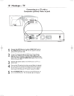
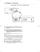
Hookups - TV (cont'd) 11 Connecting to a TV with Component Video In Jacks COMPONENT VIDEO OUT PWCr PWCw Y AM FM (7Ω) AM/FM ANTENNA CENTER AUDIO OUT AUDIO IN LINE OUT L S-VIDEO VIDEO OUT OUT DIGITAL OUT WOOFER LINE OUT R TV AUX OPTICAL COAXIAL FR FL C SR SL + + SPEAKER (4Ω) 1 Connect the DVD Receiver's Pr/Cr Pb/Cb Y COMPONENT VIDEO OUT jacks to the matching Pr/Cr Pb/Cb Y VIDEO IN jacks on the TV. You will need a component video cable (Green-Y; BluePb/Cb; Red- Pr/Cr) (not supplied). Match the cable colors to the jack colors. 2 To hear TV channels through the DVD Home Cinema System, connect the supplied red and white audio cables to the DVD Receiver's red/white, right/left (TV) AUDIO IN jacks and to the TV'S right/left AUDIO OUT jacks. Match the cable colors to the jack colors. 3 Connect the power cords of the DVD Receiver and TV to a power outlet. 4 Turn on the TV and set it to the correct Component Video In channel. Go to the lowest TV channel and change channels down until you find the Component Video In channel. (It is not channel 3 or 4 as it might be when using a VCR.) See your TV owner's manual for details. 5 Press STANDBY-ON y on the front of the DVD Receiver to turn on the DVD Receiver. The red Standby light will disappear. 6 Set VIDEO OUT to PR PB Y. Details are on page 28. TV SHAPE TV SYSTEM VIDEO OUT SCR SAVER S-VIDEO PR PB Y/SCART PR PB Y Helpful Hint • On the TV, the Component Video In jacks may be labeled YUV or Pr/Cr Pb/Cb Y and may be red, blue, and green.
-
 1
1 -
2
-
3
-
4
-
5
-
 6
6 -
 7
7 -
 8
8 -
 9
9 -
 10
10 -
 11
11 -
 12
12 -
 13
13 -
 14
14 -
 15
15 -
 16
16 -
17
-
18
-
19
-
20
-
21
-
22
-
23
-
24
-
25
-
26
-
27
-
28
-
29
-
30
-
31
-
32
-
33
-
34
-
35
-
36
-
37
-
38
-
39
-
40
-
41
-
42
-
43
-
44
 |
 |
