Maytag MEDE900VJ Installation Instructions
Maytag MEDE900VJ - Performance 7.5 cu. Ft. Steam Electric Dryer Manual
 |
UPC - 883049144764
View all Maytag MEDE900VJ manuals
Add to My Manuals
Save this manual to your list of manuals |
Maytag MEDE900VJ manual content summary:
- Maytag MEDE900VJ | Installation Instructions - Page 1
CONNECT INLET HOSE (STEAM MODELS 14 LEVEL DRYER 15 COMPLETE INSTALLATION 15 TROU BLESHOOTING 15 DRYER SAFETY Your safety and the safety of others are very important. We have provided many important safety messages in this manual and on your appliance. Always read and obey all safety messages - Maytag MEDE900VJ | Installation Instructions - Page 2
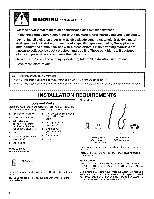
- Install the clothes dryer according to the manufacturer's instructions and local codes. - Do not install a clothes dryer with flexibJe plastic venting materials, if fle×ible metal (foiJ type) duct is instaJled, it must be of a specific type identified by the appliance manufacturer as suitable for - Maytag MEDE900VJ | Installation Instructions - Page 3
A sturdy floor to support the total dryer weight of 200 Ibs (90.7 kg). The combined weight of a companion appliance should also be considered. A level floor with a maximum slope of 1" (25 mm) under entire dryer. If slope is greater than 1" (25 mm), install Extended Dryer Feet Kit, Part Number 279810 - Maytag MEDE900VJ | Installation Instructions - Page 4
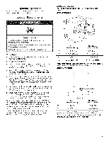
dimensions are recommended for this dryer. This dryer has Companion appliance spacing should also be considered. Custom undercounter installation - Dryer only , 0" (0 mm) spacing is allowed. Recessed or closet installation - Dryer on pedestal ,_ 18" min.* B--4 D*l E--4 F _ Steam (Electric or Gas - Maytag MEDE900VJ | Installation Instructions - Page 5
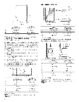
is allowed. Recommended installation spacing for recessed or closet installation, with stacked washer and dryer The dimensions shown are for the recommended spacing. 48 in. 2 * (310 Title 24, HUD Part 280) or Standard CAN/CSA-Z240 MH. Mobile home installations require: All Dryers: • Metal exhaust - Maytag MEDE900VJ | Installation Instructions - Page 6
be used when the appliance is installed in with clothes dryers. The kit should contain: • A UL listed 30-amp power supply cord, rated 120/ GROUNDING iNSTRUCTiONS [] For a grounded, cord-connected dryer: This dryer must be service representative or personnel if you are in doubt as to whether the dryer - Maytag MEDE900VJ | Installation Instructions - Page 7
the wire insulation on the power supply cord is inside the strain relief. The strain relief should have a tight fit with the dryer cabinet and be in a horizontal position. Do not further tighten strain relief screws at this point. C A. Removableconduit connector B. Hole below terminalblock - Maytag MEDE900VJ | Installation Instructions - Page 8
use of 3-wire connections. B F 4. Now complete installation following instructions for your type of electrical connection: 4-wire (recommended) 3-wire (127 ram) 3-wire receptacle (NEMA type 10-30R) 30-amp, dryer mpoinwimerumsu,pply cord* A fused dciirsccuoitnnbercetakoerr box* A UL listed, 120/ - Maytag MEDE900VJ | Installation Instructions - Page 9
relief screws. 6. Insert tab of terminal block cover into slot of dryer rear panel. Secure cover with hold-down screw. 7, You have completed 3-wire connections. Direct wire cable must have 5 ft (1.52 m) of extra length so dryer can be moved if needed. Strip 5" (127 mm) of outer covering from end of - Maytag MEDE900VJ | Installation Instructions - Page 10
: Direct wire Use where local codes permit connecting cabinet-ground conductor to neutral wire. Direct wire cable must have 5 ft (1.52 m) of extra length so dryer can be moved if needed. Strip 31/£' (89 mm) of outer covering from end of cable. Strip insulation back 1" (25 mm). If using 3-wire cable - Maytag MEDE900VJ | Installation Instructions - Page 11
instructions can dryer MUST BE EXHAUSTED OUTDOORS. IMPORTANT: Observe all governing codes and ordinances. The dryer Review vent system chart. Modify existing vent system if necessary to achieve the best Service. For more information, see the "Assistance or Service" section. Rigid metal vent • For best - Maytag MEDE900VJ | Installation Instructions - Page 12
extended and supported when the dryer is problems and health problems. Plan Vent System Choose your exhaust installation type Recommended exhaust installations Typical installations vent the dryer from the rear of the dryer instructions can result in death, fire, electrical shock, or serious injury - Maytag MEDE900VJ | Installation Instructions - Page 13
available for purchase. Please see the "Assistance or Service" section to order. • Over-the-Top Installation: Part Number 4396028 Periscope Installation (For use with dryer vent to wall vent mismatch): Part Number 4396037 - 0" (0 mm) to 18" (457 mm) mismatch Part Number 4396011 - 18" (457 mm) to 29 - Maytag MEDE900VJ | Installation Instructions - Page 14
seated on fill valve connector. CONNECT INLET HOSE (STEAM MODELS) The dryer must be connected to the cold water faucet using the new inlet hoses. Do not use old hoses. 1. Turn cold water faucet off and remove washer inlet hose. 2. Remove old rubber washer from inlet hose and replace with new rubber - Maytag MEDE900VJ | Installation Instructions - Page 15
part replacement or repair. All Models: 13. Select a Timed Dry heated cycle, and start the dryer. Do not select the Air Only Temperature setting. If the dryer away. TROUBLESHOOTING First try the solutions suggested here and possibly avoid the cost of a service call... Dryer Operation Dryer will - Maytag MEDE900VJ | Installation Instructions - Page 16
cleaned. "E" Variable (El, E2, E3) service codes: Call for service. Dryer Results Clothes are not drying satisfactorily, drying times are dryer requires a minimum of 1" (25 mm) of airspace, and, for most installations, the rear of the dryer requires 5" (127 mm). See the Installation Instructions.
-
 1
1 -
 2
2 -
 3
3 -
 4
4 -
 5
5 -
 6
6 -
 7
7 -
8
-
9
-
10
-
11
-
12
-
13
-
14
-
15
-
16
 |
 |
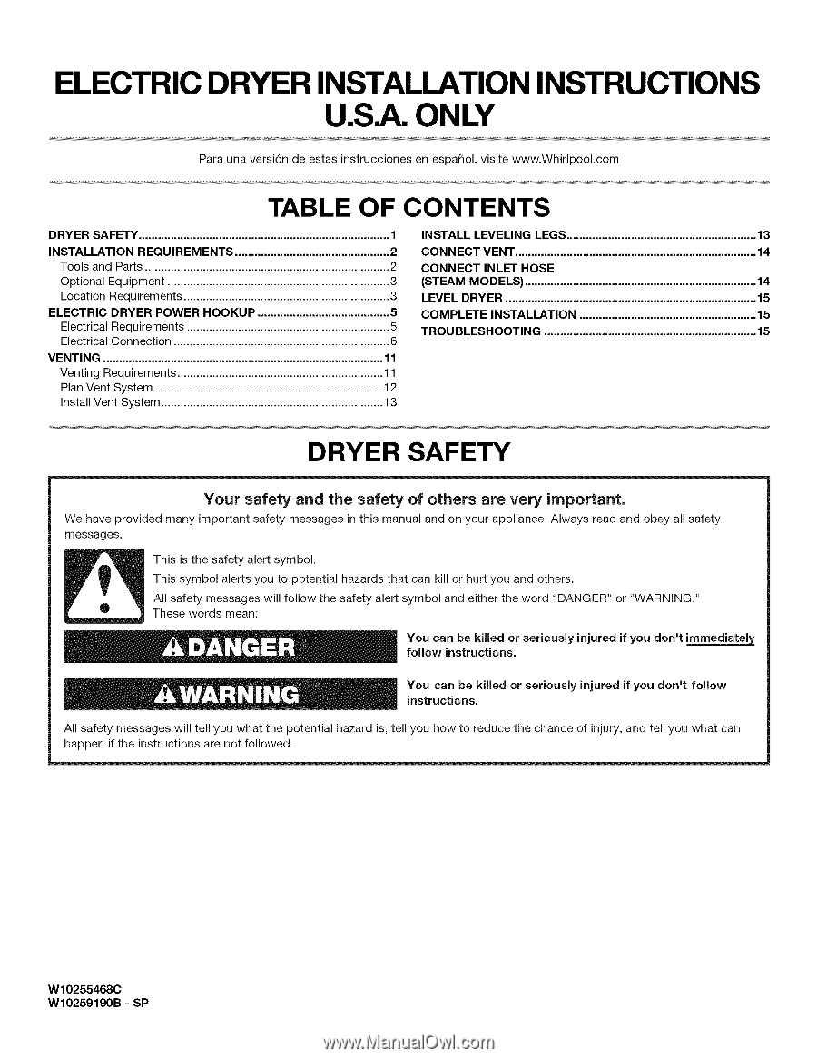
ELECTRIC DRYER INSTALLATION INSTRUCTIONS
U.S.A. ONLY
Para una versi6n de estas instrucciones
en espa_ol,
visite www.Whirlpool.com
TABLE
OF CONTENTS
DRYER SAFETY
..............................................................................
1
INSTALLATION
REQUIREMENTS
................................................
2
Tools
and Parts
............................................................................
2
Optional
Equipment
.....................................................................
3
Location Requirements
................................................................
3
ELECTRIC
DRYER POWER
HOOKUP
.........................................
5
Electrical
Requirements
...............................................................
5
Electrical Connection
...................................................................
6
VENTING
.......................................................................................
11
Venting
Requirements
................................................................
11
Plan Vent System
.......................................................................
12
Install
Vent System
.....................................................................
13
INSTALL LEVELING
LEGS
...........................................................
13
CONNECT
VENT
...........................................................................
14
CONNECT
INLET HOSE
(STEAM MODELS)
........................................................................
14
LEVEL DRYER
..............................................................................
15
COMPLETE
INSTALLATION
.......................................................
15
TROU BLESHOOTING
..................................................................
15
DRYER SAFETY
Your
safety
and
the
safety
of
others
are
very
important.
We have provided
many important
safety messages
in this manual and on your appliance.
Always read and obey all safety
messages.
This is the safety alert symbol.
This symbol
alerts you to potential
hazards that can kill or hurt you and others.
All safety messages
will follow
the safety alert symbol
and either the word
"DANGER"
or "WARNING."
These words mean:
You can
be
killed or seriously
injured if you
don't
immediatel_
follow
instructions.
You
can
be
killed
or
seriously
injured if you
don't
follow
instructions.
All safety messages
will tell you what the potential
hazard
is,
tell you how to reduce the chance
of
injury,
and tell you what can
happen
if the instructions
are not followed.
W10255468C
W10259190B
-
SP