Maytag MEDE900VJ Installation Instructions - Page 10
intoslotofdryer
 |
UPC - 883049144764
View all Maytag MEDE900VJ manuals
Add to My Manuals
Save this manual to your list of manuals |
Page 10 highlights
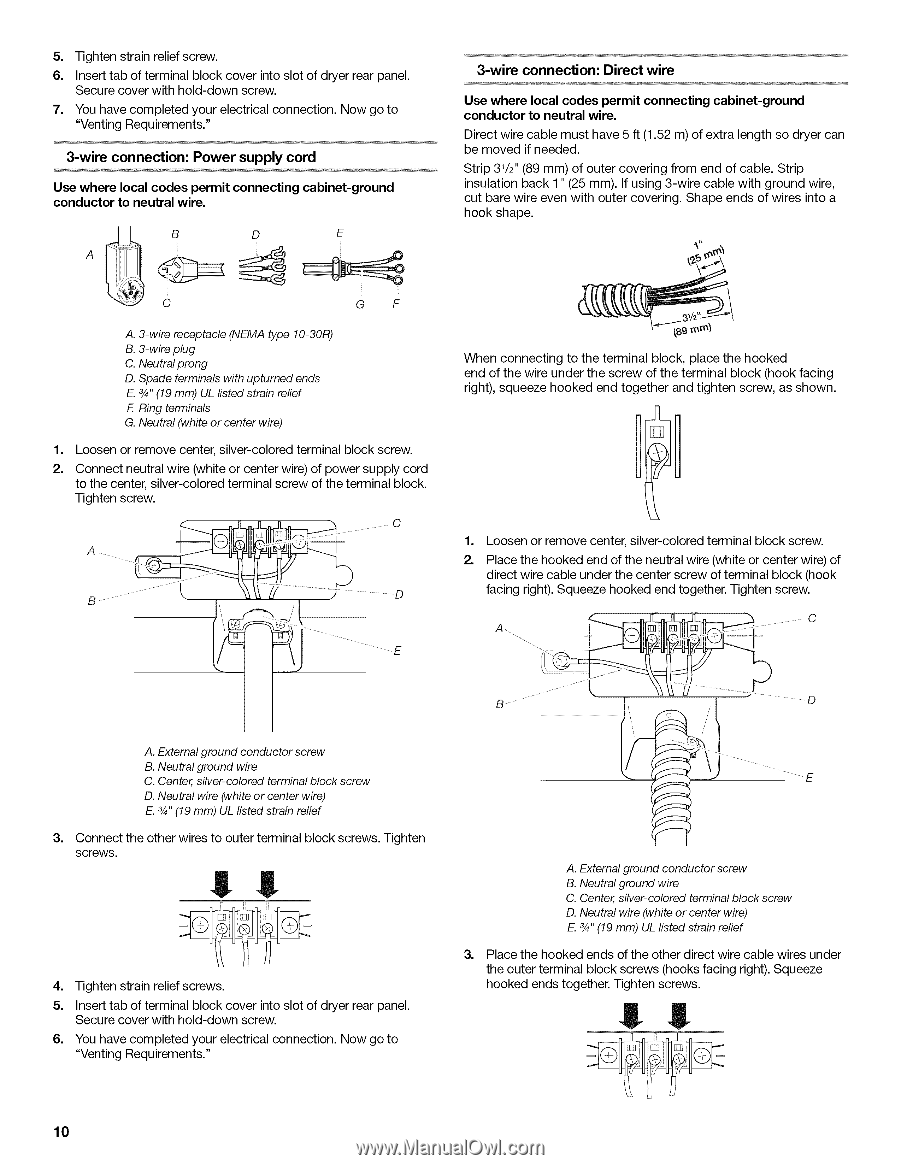
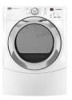
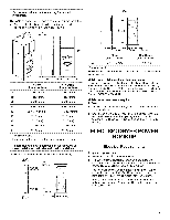
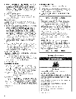
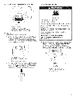
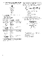
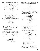
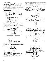
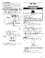
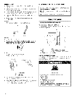
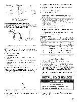
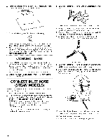
5. Tightesntrainreliesfcrew. 6. Insertat bofterminbalocckoveirntoslotofdryerreapr anel. Securceovewr ithhold-dowsncrew. 7. Youhavecompletyeoduer lectriccaol nnectioNno.wgoto "VentinRgequirements." 3-wire connection: Power supply cord Use where local codes permit connecting cabinet-ground conductor to neutral wire. B D E 3-wire connection: Direct wire Use where local codes permit connecting cabinet-ground conductor to neutral wire. Direct wire cable must have 5 ft (1.52 m) of extra length so dryer can be moved if needed. Strip 31/£' (89 mm) of outer covering from end of cable. Strip insulation back 1" (25 mm). If using 3-wire cable with ground wire, cut bare wire even with outer covering. Shape ends of wires into a hook shape. C GF A. 3-wire receptacle (NEMA type 10-30R) B. 3-wire plug C. Neutral prong D. Spade terminals with upturned ends E. 3/4"(19 mm) UL listed strain relief E Ring terminals G. Neutral (white or center wire) 1, Loosen or remove center, silver-colored terminal block screw. 2. Connect neutral wire (white or center wire) of power supply cord to the center, silver-colored terminal screw of the terminal block. Tighten screw. A c B ••• •D When connecting to the terminal block, place the hooked end of the wire under the screw of the terminal block (hook facing right), squeeze hooked end together and tighten screw, as shown. 1, Loosen or remove center, silver-colored terminal block screw. 2. Place the hooked end of the neutral wire (white or center wire) of direct wire cable under the center screw of terminal block (hook facing right). Squeeze hooked end together. Tighten screw. B ii o A. External ground conductor screw B. Neutral ground wire C. Center, silver-colored terminal block screw D. Neutral wire (white or center wire) E. 3/4"(19 mm) UL listed strain relief 3, Connect the other wires to outer terminal block screws. Tighten screws. 4. Tighten strain relief screws. 5. Insert tab of terminal block cover into slot of dryer rear panel. Secure cover with hold-down screw. 6. You have completed your electrical connection. Now go to "Venting Requirements." A. External ground conductor screw B. Neutral ground wire C. Center, silver-colored terminal block screw D. Neutral wire (white or center wire) E. 3/4"(19 mm) UL listed strain relief 3, Place the hooked ends of the other direct wire cable wires under the outer terminal block screws (hooks facing right). Squeeze hooked ends together. Tighten screws. l! 10
-
 1
1 -
2
-
3
-
4
-
 5
5 -
 6
6 -
 7
7 -
 8
8 -
 9
9 -
 10
10 -
 11
11 -
 12
12 -
 13
13 -
 14
14 -
 15
15 -
16
 |
 |