Maytag MEDE900VJ Installation Instructions - Page 7
Style, Power supply cord strain relief, Direct wire strain relief, Fire Hazard, UL listed,
 |
UPC - 883049144764
View all Maytag MEDE900VJ manuals
Add to My Manuals
Save this manual to your list of manuals |
Page 7 highlights
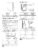
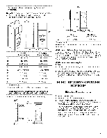
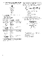
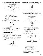
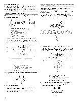
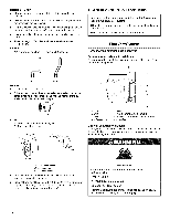
2= Remove the hold-down screw and terminal block cover. Style 2: Direct wire strain relief A. Neutral ground wire B. External ground conductor screw C. Center, silver-colored terminal block screw D. Terminal block cover and hold-down screw 3. Install strain relief. Style 1: Power supply cord strain relief Remove the screws from a 3/4" (19 mm) UL listed strain relief (UL marking on strain relief). Put the tabs of the two clamp sections into the hole below the terminal block opening so that one tab is pointing up and the other is pointing down, and hold in place. Tighten strain relief screws enough to hold the two clamp sections together. A Fire Hazard Use 10 gauge solid copper wire. Use a UL listed strain relief. Disconnect power before making electrical connections. Connect neutral wire (white or center wire} to center terminal (silver}. Ground wire (green or bare wire} must be connected to green ground connector. Connect remaining 2 supply wires to remaining 2 terminals (gold}. Securely tighten all electrical connections. Failure to do so can result in death, fire, or electrical shock. • Unscrew the removable conduit connector and any screws from a 3/4" (19 mm) UL listed strain relief (UL marking on strain relief). Put the threaded section of the strain relief through the hole below the terminal block opening. Reaching inside the terminal block opening, screw the removable conduit connector onto the strain relief threads. A. Strain relief tab pointing up B. Hole below terminal block opening C. Clamp section D. Strain relief tab pointing down Put power supply cord through the strain relief. Be sure that the wire insulation on the power supply cord is inside the strain relief. The strain relief should have a tight fit with the dryer cabinet and be in a horizontal position. Do not further tighten strain relief screws at this point. C A. Removableconduit connector B. Hole below terminalblock opening C. Strain relief threads
-
 1
1 -
 2
2 -
 3
3 -
 4
4 -
 5
5 -
 6
6 -
 7
7 -
 8
8 -
 9
9 -
 10
10 -
 11
11 -
 12
12 -
13
-
14
-
15
-
16
 |
 |