Maytag MMV4205BAQ Installation Instructions - Page 10
D. Aligning, The Wall Plate - template for installation
 |
View all Maytag MMV4205BAQ manuals
Add to My Manuals
Save this manual to your list of manuals |
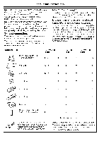
Page 10 highlights
Installation Instructions D. ALIGNING THE WALL PLATE i i REAR WALk TEMPLATE Centedine notches Draw a Vertical Line on Wall from Center __ _
-
 1
1 -
2
-
3
-
4
-
 5
5 -
 6
6 -
 7
7 -
 8
8 -
 9
9 -
 10
10 -
 11
11 -
 12
12 -
 13
13 -
 14
14 -
 15
15 -
16
-
17
-
18
-
19
-
20
-
21
-
22
-
23
-
24
-
25
-
26
-
27
-
28
-
29
-
30
-
31
-
32
-
33
-
34
-
35
-
36
-
37
-
38
-
39
-
40
-
41
-
42
-
43
-
44
-
45
-
46
-
47
-
48
-
49
-
50
-
51
-
52
-
53
-
54
-
55
-
56
-
57
-
58
-
59
-
60
-
61
-
62
-
63
-
64
-
65
-
66
-
67
-
68
-
69
-
70
-
71
-
72
 |
 |

Installation
Instructions
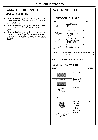
D. ALIGNING
THE WALL PLATE
Horizontal
Line
I'''-
7
Area E
i
i
REAR
WALk
TEMPLATE
_;:_,,_!_:
........................
Centedine
Draw a Vertical Line
notches
on Wall from Center
__
_<___ of Top Cabinet
o
o
o
o
o
o
o
o
o
o
Hole C
CAUTION:
Wear
gloves
to avoid
cutting
fingers
on sharp
edges.
Hole B
Horizontal
Line
Draw
a Horizontal
line on wall
from
bottom
of
"Rear
Wall
Template".
1,
Draw
a Vertical
line on the wall
at the center
of the
30" wide
space.
2.
Draw
a Horizontal
line on the walt at the bottom
of
"Rear
Wall
Template".
3.
Drill 5/8"
holes for toggle
bolts on 3 locations
(Hole
A, Hole
B, Hole
C) but if the location
of hole
is same
as that of stud, drill a 3/16"
hole for wood
screw.
In other words,
toggle
bolt can not be used
to the location
of stud.
NOTE:
DO NOT
MOUNT
THE
PLATE
AT THIS
TIME.
NOTE:
Holes A, B and C are inside
area
E. If none
of
A, B and C is in a stud, find a stud somewhere
in area
E and draw
a forth
circle
to line up with
the stud.
It is
important
to use at least
one
wood
screw
mounted
firmly
in a stud
to support
the weight
of the
microwave.
Set the
mounting
plate
aside.
10