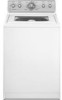
Maytag MVWC700VW Installation Instructions
Maytag MVWC700VW - Centennial Washer Manual
 |
View all Maytag MVWC700VW manuals
Add to My Manuals
Save this manual to your list of manuals |
Maytag MVWC700VW manual content summary:
- Maytag MVWC700VW | Installation Instructions - Page 1
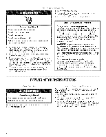
LA LAVEUSE Table of Contents/Table des matibres WASHER SAFETY 1 SECURITE DE LA LAVEUSE 9 iNSTALLATiON REQUIREMENTS Tools and Parts Location Requirements Drain System Electrical Requirements iNSTALLATiON iNSTRUCTiONS Before You Start 2 EXIGENCES D'INSTALLATION 9 2 Outillages et - Maytag MVWC700VW | Installation Instructions - Page 2
installation. The parts supplied are in the washer basket. Parts needed (not provided m Inlet hoses with washer}: m Flat washers To order: m Call the dealer from whom you purchased your washer. m Reference the toll-free number on the front page of the Washer User Instructions. m Visit the - Maytag MVWC700VW | Installation Instructions - Page 3
to support the washer weight (washer, water, and load) of 315 Ibs (143 kgs). Do not store or operate your washer in temperatures at or below 32°F (0°C). Some water can remain in the washer and can cause damage in tow temperatures. See "Washer Care" in the Washer User Instructions for winterizing - Maytag MVWC700VW | Installation Instructions - Page 4
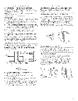
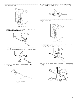
within approximately 3 ft (90 cm) of its final location. 2= The washer must be in the upright position and not tilted before removing the shipping material. 3. Locate the yellow shipping materials on the rear of the machine, near the bottom. Follow the steps for your particular model, either the one - Maytag MVWC700VW | Installation Instructions - Page 5
cord 1. Remove power plug and yellow strap from machine base to release the rear beveling system. Looped power cord 1. Firmly grasp the yellow shipping strap and pull until both ends are completely removed from washer. 3. Confirm that the power cord restraint (A) and pin (B) are removed. U 2. - Maytag MVWC700VW | Installation Instructions - Page 6
to water leakage. Read and follow these instructions. The drain hose is connected to your washer and is stored inside the washer cabinet. The washer must be connected to the water faucets using new inlet hoses (not provided). Do not use old hoses. Insert new flat washers into each end of the inlet - Maytag MVWC700VW | Installation Instructions - Page 7
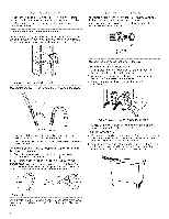
the front leveling feet 1. Prop up the front of the washer about 4" (10.2 cm) with a wood block or similar object. The block needs to support the weight of the washer. 5. Attach the cold water hose to the top (or right-hand, on some models) inlet valve. 6. Screw on coupling by hand until it is - Maytag MVWC700VW | Installation Instructions - Page 8
on the washer. 10. Read "Washer Use" in the Washer User Instructions. 11. To test and to clean your washer, measure 1_of the normal recommended amount of powdered or liquid detergent and pour it into the washer basket or detergent dispenser (on some models). Close the lid. Select any cycle, and then - Maytag MVWC700VW | Installation Instructions - Page 9
le danger potentiel et vous disent comment r_duire le risque de blessure et ce qui peut se produire en cas de non-respect des instructions. EXIGENCES ffINSTALLATION Rassembter les outils et pi_ces necessaires avant de commencer I'instatlation. Les pi_ces fournies se trouvent darts le panier de la - Maytag MVWC700VW | Installation Instructions - Page 10
CU). nr_sidud'eaudanslalaveusreisqudee causedresdommage&sbassteemperatuVreo.i"rEntretiednela laveusep"oudr esrenseignemesnutrst'hiverisation. i (99 crn) Installatiodnartsunencastremeonut un placard \ Les dimensions en haut et en bas de dimensions minimates (C). Des portes & jalousies avec - Maytag MVWC700VW | Installation Instructions - Page 11
enlever la broche de liaison a la terre. Ne pas utiliser un adaptateur. Ne pas utiliser un cfible de ral|onge. Le non=respect de ces instructions peut causer un d_c_s, un incendie ou un choc _lectrique. [] Atimenter la laveuse au moyen d'un circuit individuel de 120 volts, 60 Hz, CA seutement - Maytag MVWC700VW | Installation Instructions - Page 12
Cordon d'alimentation droit Pour retirer le cordon d'atimentation du dispositif d'immobilisation, enfoncer le cordon d'alimentation, appuyer sur TAB (languette), puis tirer sur le cordon d'atimentation pour le sortir. Cordon d'alimentation droit 1= 0ter la fiche du cordon d'atimentation et la - Maytag MVWC700VW | Installation Instructions - Page 13
{i_:_i:ii_:!!_ Drain de plancher Veiller & raccorder correctement le tuyau de vidange pour qu'aucune fuite d'eau ne puisse det6riorer le ptancher. Life les instructions ci-dessous et les suivre & la tettre. Le tuyau de vidange est connecte & la taveuse et est remise l'interieur de la caisse de la - Maytag MVWC700VW | Installation Instructions - Page 14
Raccorder les tuyaux d'arriv_e d'eau & la laveuse A (Sur certains modules) (Sur certains modeles) Inspection = recherche des fuites Ouvrir tes robinets d'eau; inspecter pour rechercher les fuites. Une petite quantite d'eau peut penetrer dans la laveuse. II suffira de - Maytag MVWC700VW | Installation Instructions - Page 15
nivellement avant 1= Soulever I'avant de la laveuse d'environ 4" (10,2 cm) avec un bloc de bois ou un objet sembtabte. Le bloc dolt pouvoir supporter le poids de la laveuse. Etapes dans I'emplacement final 1. Faire glisser la laveuse & son emplacement final. 2. Incliner la laveuse vers l'avant pour - Maytag MVWC700VW | Installation Instructions - Page 16
adaptateur. Ne pas utiliser un c&ble de ra|longe. Le non=respect de ces instructions peut causer un d_cbs, un incendie ou un choc _lectrique. 8° Brancher sur une prise programme pour mettre la laveuse en marche. Laisser la machine executer un programme complet. W10200331B SP PN W10200662B © 2008
-
 1
1 -
 2
2 -
 3
3 -
 4
4 -
 5
5 -
 6
6 -
 7
7 -
8
-
9
-
10
-
11
-
12
-
13
-
14
-
15
-
16
 |
 |
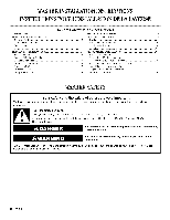
WASHERINSTALLATIONINSTRUCTIONS
INSTRUCTIONS POUR L'INSTALLATIONDE LA LAVEUSE
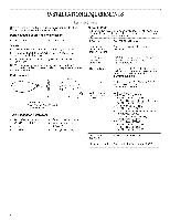
Table
of Contents/Table
des matibres
WASHER
SAFETY
..................................................................................
1
iNSTALLATiON
REQUIREMENTS
.........................................................
2
Tools and Parts
....................................................................................
2
Location
Requirements
........................................................................
3
Drain System
.......................................................................................
3
Electrical
Requirements
.......................................................................
4
iNSTALLATiON
iNSTRUCTiONS
...........................................................
4
Before You Start
..................................................................................
4
Remove
Shipping
Materials
.................................................................
4
Connect
Drain Hose
............................................................................
6
Connect
the Inlet Hoses
......................................................................
6
Secure the Drain Hose
.........................................................................
7
Level the Washer
.................................................................................
7
Complete
Installation
...........................................................................
8
SECURITE
DE LA LAVEUSE
..................................................................
9
EXIGENCES
D'INSTALLATION
..............................................................
9
Outillages
et pieces
.............................................................................
9
Exigences
d'emplacement
................................................................
10
Syst_me
de vidange
..........................................................................
10
Sp6cifications
61ectriques
.................................................................
11
iNSTRUCTiONS
D'INSTALLATION
.....................................................
11
Avant de commencer
........................................................................
11
Retrait
du mat6riei
d'expedition
........................................................
11
Raccordement
du tuyau de vidange
.................................................
13
Raccordement
des tuyau× d'arriv6e
d'eau
........................................
13
Immobilisation
du tuyau de vidange
..................................................
14
R6giage de I'aplomb
de ia laveuse
....................................................
15
Achever
I'installation
..........................................................................
16
WASHER SAFETY
Your
safety
and
the safety
of others
are very
important.
We
have
provided
many
important
safety
messages
in this
manual
and
on your
appliance.
Always
read
and
obey
all safety
messages.
This
is the safety alert symbol.
This symbol
alerts you to potential
hazards that can kill or hurt you and others.
All safety messages
will follow the safety alert symbol and either the word "DANGER"
or "WARNING."
These words mean:
You can be killed or seriously
injured if you don't immediately
follow
instructions.
You can be
killed
or seriously
injured
if you don't
follow
instructions.
All safety messages
will tell you what the potential
hazard is, tell you how to reduce the chance
of injury, and tell you what can
happen
if the instructions
are not followed.
W10200331B