Motorola WR850G User Manual - Page 13
Front of Router, LED Description - password
 |
UPC - 612572095027
View all Motorola WR850G manuals
Add to My Manuals
Save this manual to your list of manuals |
Page 13 highlights
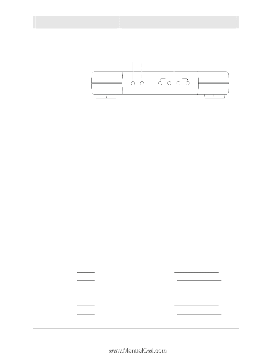
SECTION 1 OVERVIEW Front of Router The following illustration shows the BR700 front panel: 12 3 Power Modem Local Network 1 2 3 4 The LEDs of the router indicate its operational status. LED 1. Power LED Description The underlined items indicate activity on the network. Condition Color Status ON Green The device is powered on and operating normally. Blinking Green Firmware update is in progress. Blinking/OFF Red The power LED turns RED as soon as the reset button is depressed. If the reset button is held down for more than 5 seconds, the LED starts to blink and the router's default user name, password, private LAN IP address, and private subnet mask address will be restored. The LED then turns off until the reset button is released. The power LED keeps blinking RED if the firmware is corrupted, indicating the firmware needs to be restored. 2. Modem OFF ON Blinking ON/Blinking ON/Blinking None No external Ethernet device has been attached and detected. The Ethernet link is down. Red The WAN interface has been disabled by the firmware. Red The WAN connection has lost IP connectivity with its default gateway even though the Ethernet link is still up. Or the WAN connection repair procedure is still in progress. Amber 10BaseT link detected/active traffic present. Green 100BaseT link detected/active traffic present. 3. LAN (x4) OFF ON/Blinking ON/Blinking None Amber Green No external Ethernet device has been attached and detected. The Ethernet link is down. 10BaseT link detected/active traffic present. 100BaseT link detected/active traffic present. 1-8 SECTION 1, OVERVIEW
-
 1
1 -
2
-
3
-
4
-
5
-
6
-
7
-
 8
8 -
 9
9 -
 10
10 -
 11
11 -
 12
12 -
 13
13 -
 14
14 -
 15
15 -
 16
16 -
 17
17 -
 18
18 -
19
-
20
-
21
-
22
-
23
-
24
-
25
-
26
-
27
-
28
-
29
-
30
-
31
-
32
-
33
-
34
-
35
-
36
-
37
-
38
-
39
-
40
-
41
-
42
-
43
-
44
-
45
-
46
-
47
-
48
-
49
-
50
-
51
-
52
-
53
-
54
-
55
-
56
-
57
-
58
-
59
-
60
-
61
-
62
-
63
-
64
-
65
-
66
-
67
-
68
-
69
-
70
-
71
-
72
-
73
-
74
-
75
-
76
-
77
-
78
 |
 |