NEC NEC-80570 User Guide
NEC NEC-80570 - 22 Button Standard Telephone Manual
 |
UPC - 714627059029
View all NEC NEC-80570 manuals
Add to My Manuals
Save this manual to your list of manuals |
NEC NEC-80570 manual content summary:
- NEC NEC-80570 | User Guide - Page 1
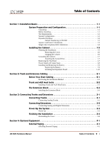
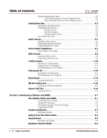
1-6 (using extension numbers Guide that came with your system for more. 2. Trunk and Extension Cabling 3. Connecting Trunks and Extensions 4. Optional Equipment 5. Maintenance Options and SMDR 6. Specifications and Parts Hardware Manual 03.**.** For additional resources, visit our Technical Support - NEC NEC-80570 | User Guide - Page 2
. It is intended for the use of its customers and service personnel, and should be read in its entirety before attempting to install or program the system. Any comments or suggestions for improving this manual would be appreciated. Forward your remarks to: NEC America, Inc., Corporate Networks Group - NEC NEC-80570 | User Guide - Page 3
Numbering in DS1000 1-2 System Load Factor Calculations 1-3 Single Line Telephone REN Limitations 1-4 Installing the Cabinet 1-5 Planning the Installation 3-4 Section 4: Optional Equipment 4-1 External Paging 4-1 Installing External Paging 4-1 DS1000 Hardware Manual Table of Contents x i - NEC NEC-80570 | User Guide - Page 4
-Mount Kit 4-12 Installing the Wall-Mount Kit 4-12 Wall-Mounting a Key Telephone 4-12 Desk Stand 4-14 Using the Desk Stand 4-14 REJ Recording Jack 4-15 Installing the REJ Recording Jack Resetting Your System 5-5 Database Transfer Utility 5-6 ii x Table of Contents DS1000 Hardware Manual - NEC NEC-80570 | User Guide - Page 5
of Contents About the Database Transfer Utility 5-6 Connecting the Systems 5-6 Important Database Transfer Utility Notes 5-7 Using the Database Transfer Utility 5-7 Section 6: Specifications and Parts 6-1 Specifications 6-1 Parts List 6-6 Index DS1000 Hardware Manual Table of Contents x iii - NEC NEC-80570 | User Guide - Page 6
Table of Contents iv x Table of Contents DS1000 Hardware Manual - NEC NEC-80570 | User Guide - Page 7
site must meet the requirements outlined in the Standard Practices Manual. Site Requirements The common equipment is contained in the wall you about how much space your system requires. System Configuration Using the factory installed default configuration, your DS1000 system provides: Base - NEC NEC-80570 | User Guide - Page 8
Groups, and Ring Groups. q Support for built-in IntraMail Voice Mail extension number is used to call the Numbering Stations (Telephones) Digital Station number. - For example, station number 1 uses extension number 300 (1 + 299). Trunks 1 uses extension number 101 (1 + 100 - NEC NEC-80570 | User Guide - Page 9
the System Load Factor. Use the DS1000 System Load Telephone Analog Door Box 24-Button DSS Console 110-Button DSS Console 2-OPX Module 1 1 0 1 2 Total DSS Consoles installed cannot exceed 4 3 Item 1: Total load for this configuration Item 2: Maximum allowable load 30 DS1000 Hardware Manual - NEC NEC-80570 | User Guide - Page 10
Line Telephone REN Limitations Please note the following when installing single line telephones analog telephones ring simultaneously for outside calls (as do all analog telephones connected to up all analog telephones connected to the Many phones with electronic ringers have significantly lower - NEC NEC-80570 | User Guide - Page 11
adequate (see Figure 1-1 Installation Layout below). Mount this backboard using suitable fasteners, taking care to adhere 1 to standard installation 80200 - 37 Trunk/AUX RJ-25C Jacks 4' DS1000 Hardware Manual Station Blocks To telco ground Surge Protector Dedicated AC Outlet Figure - NEC NEC-80570 | User Guide - Page 12
"backed out" about 3/16" from the MDF backboard. 2. Hang the cabinet as shown. 80200 - 3 11 - 3/16" Figure 1-3: Hanging the Cabinet 1-6 x Section 1: Installation Basics DS1000 Hardware Manual - NEC NEC-80570 | User Guide - Page 13
!! 1 You must connect your system to a known earth ground according to the following instructions. To attach the ground wire (Figure 1-4): 1. Loosen the lug on the cabinet's ground , 8 analog extensions, and 2 analog door boxes. DS1000 Hardware Manual Section 1: Installation Basics x 1-7 - NEC NEC-80570 | User Guide - Page 14
the site's AC line. These problems can include improperly wired outlets and power surges. In normal operation, you should never need to replace the power supply AC input fuses. To replace a fuse: (Figure 1-5): 1. Be sure your system's power cord is unplugged. 2. Using a commercially-available fuse - NEC NEC-80570 | User Guide - Page 15
3 Volt Lithium cell battery or equivalent. (This battery is not available from NEC.) 4. Verify that the system's programmed data is intact. 5. Discard the manufacturer. Dispose of used batteries according to the manufacturer's instructions. DS1000 Hardware Manual Section 1: Installation Basics x - NEC NEC-80570 | User Guide - Page 16
the Expansion Board To install the Expansion Board (Figure 1-7): 1. Be sure your system's power cord is unplugged. The Expansion Board is not hot-swappable. 2. Plug in the Expansion Board as shown 1-7: Installing the Expansion Board 1-10 x Section 1: Installation Basics DS1000 Hardware Manual - NEC NEC-80570 | User Guide - Page 17
!! Important !! • Install telephones connected to the Main Equipment 25C modular jacks. q Extension Blocks The system uses a 66M1-50 extension block and a second Line Interface (Future) 4- or 6-Conductor Line Cord Extension Block AC Outlet Figure 2-1: Installation Layout DS1000 Hardware Manual - NEC NEC-80570 | User Guide - Page 18
Arrange your mod jacks trunk according to Figure 2-1 Installation Layout on page 2-1. 2. Using standard 6-conductor line cords, connect each mod jack to the appropriate plug in the Main Equipment Cabinet. See (3T) GRN-WHT (3R) 2-2 x Section 2: Trunk and Extension Cabling DS1000 Hardware Manual - NEC NEC-80570 | User Guide - Page 19
VIO-SLT NC 50 50 SLT-VIO NC 25 80200 - 5 ANALOG EXTENSIONS 316-319 (BASE) ANALOG EXTENSIONS 320-323 (EXPANSION) Figure 2-4: Extension Assignments 2 DS1000 Hardware Manual Section 2: Trunk and Extension Cabling x 2-3 - NEC NEC-80570 | User Guide - Page 20
The Extension Block 2-4 x Section 2: Trunk and Extension Cabling DS1000 Hardware Manual - NEC NEC-80570 | User Guide - Page 21
RJ-11C jacks. Review the illustration below. 2. Wire the additional modular jacks as shown. 3. Plug line cords from the telco mod jacks to the system mod jacks as shown. 80200 - 13 To CO Figure 3-1: Connecting Analog Trunks DS1000 Hardware Manual Section 3: Connecting Trunks and Extensions x 3-1 - NEC NEC-80570 | User Guide - Page 22
connect extensions (Figure 3-2): 1. Install a modular jack for each extension within 6 feet of the telephone's location. 2. For each extension, run one-pair 24 AWG station cable from the cross-connect Connecting Extensions 3-2 x Section 3: Connecting Trunks and Extensions DS1000 Hardware Manual - NEC NEC-80570 | User Guide - Page 23
grounded. 2. Install a surge protector in the AC outlet. 3. Plug the main cabinet's AC power cord into its surge protector. 4. Be sure the Mode Switch is set to RUN, then turn on the - 1 Figure 3-4: Power LED and Mode Switch DS1000 Hardware Manual Section 3: Connecting Trunks and Extensions x 3-3 - NEC NEC-80570 | User Guide - Page 24
shown. 2. Slide the cover button to LOCK. 80200 - 15 Push button to "LOCK" position Figure 3-5: Reinstalling the Cover 3-4 x Section 3: Connecting Trunks and Extensions DS1000 Hardware Manual - NEC NEC-80570 | User Guide - Page 25
a 6-conductor line cord into the AUDIO jack on the cabinet and into the Audio modular jack. 80200 - 17 BLK BLUE GRN NC NC Page T Page R Music T Music R Page Output Music Input To AUDIO in DS1000 cabinet YEL WHT RED Figure 4-1: Installing External Paging DS1000 Hardware Manual - NEC NEC-80570 | User Guide - Page 26
on the Door Box 1 modular jack to the relay that controls the External Paging system. 2. If you are using the Door 2 relays, connect the BLK and YEL lugs on the Door Box 2 modular jack to the broadcast from the External Paging output. 4-2 x Section 4: Optional Equipment DS1000 Hardware Manual - NEC NEC-80570 | User Guide - Page 27
to a digital station port. The Analog Door Box (P/N 92245) is a self-contained Intercom unit typically used to monitor an entrance door. A visitor at the door can press the Analog Door Box call button ( Operating the Door Box on page 4-5. DS1000 Hardware Manual Section 4: Optional Equipment x 4-3 - NEC NEC-80570 | User Guide - Page 28
Box and the extensions that should alert to the same Ring Group (1-8). q Ring Groups 1-8 are preset to use master numbers 600-607. Door Box Relay Control You normally set up Door Box 1 to control the Door Door Box control Door 2 relays. 4-4 x Section 4: Optional Equipment DS1000 Hardware Manual - NEC NEC-80570 | User Guide - Page 29
. 1. To open the relay, press FLASH key or OPEN soft key. 2. To close the relay, press FLASH key again or CLOSE soft key. 4 DS1000 Hardware Manual Section 4: Optional Equipment x 4-5 - NEC NEC-80570 | User Guide - Page 30
for a customer provided music source. Use this music source for Background Music and to the BLK and YEL lugs on the Audio modular jack. 2. Plug a 6-conductor line cord into the AUDIO jack on the cabinet and into the Audio modular jack. 80200 - x Section 4: Optional Equipment DS1000 Hardware Manual - NEC NEC-80570 | User Guide - Page 31
GRN 80200 - 21 To PFT/MDM in DS1000 cabinet NC NC NC NC YEL WHT RED PFT PFR Power Failure Telephone WHT-BLU GRN BLU-WHT RED 4 BLK YEL 625 Modular Jack Power Failure Telephone Figure 4-4: Connecting a Power Failure Telephone DS1000 Hardware Manual Section 4: Optional Equipment x 4-7 - NEC NEC-80570 | User Guide - Page 32
pin modular line cord into the telephone's DSS connector. 3. Plug the other end of the 8-pin line cord into the Personal Speed Dial numbers, since a DSS Console uses the Personal Speed Dial for the extension to which Console's keys. Refer to the Software Manual on your System Document CD for - NEC NEC-80570 | User Guide - Page 33
DSS Console To 625 Modular Jack DSS Console Keyset 4 Figure 4-6: Installing a 110-Button DSS Console 80000 - 44A DS1000 Hardware Manual Section 4: Optional Equipment x 4-9 - NEC NEC-80570 | User Guide - Page 34
2500 type single line devices (i.e., telephones, fax machines, modems, etc.) and to telco OL13B/C OPX circuits. It uses a single from the FG lug on the module to a known earth ground. 7. Plug a line cord into the 2-OPX unit and the 2-OPX's modular jack. The DS1 LED on the DS1000 Hardware Manual - NEC NEC-80570 | User Guide - Page 35
), assign an unused station number (e.g., 27) to the 2-OPX Module secondary station. (If you use station 27, the secondary station's extension number will be 326.) Refer to 9902 - Set Up Stations (DS1000) in the Software Manual on the System Document CD that came with your system for more. Note: You - NEC NEC-80570 | User Guide - Page 36
in the bottom of the wall-mount bracket. 4. Plug the line cord into the telephone's 625 modular jack. 5. Place the telephone on top of the wall-mount bracket and snap into place. 80000 - 42A Run cord through slot To wall jack Tab on phone must snap into cutout on wall mount bracket Figure 4-10 - NEC NEC-80570 | User Guide - Page 37
Snap the wall-mount bracket onto the wall plate. 2. Plug the telephone's line cord into the jack in the wall plate and into the telephone. 3. Place the telephone on top of the wall-mount bracket and snap into place. 80000 - 43A Tab on phone must snap into cutout on wall mount bracket Figure 4-11 - NEC NEC-80570 | User Guide - Page 38
desk stand in one of two positions: low and high. To use the desk stand low position (Figure 4-13): q Flip up each telephone leg until it snaps into place. To use the desk stand high position (Figure 4-13): 1. Flip up each telephone leg into the low position. 2. Push out the leg extender. 3. Slide - NEC NEC-80570 | User Guide - Page 39
the REJ wires through the guides in the telephone base. 2. Plug the REJ cable into the connector in the telephone PCB. The connector is keyed so you can't plug in the cable the wrong way. 3. Reassemble the telephone, plug in the handset, and reconnect the line cord. 4. Using an audio cable, connect - NEC NEC-80570 | User Guide - Page 40
Keyset Self Test Keyset Self Test Testing the Keyset Use the following procedure to perform a quick operational test of a keyset. To test a keyset: 1. Unplug the telephone line cord. 2. While pressing HOLD, plug the telephone back in. All the LED elements in the display will fill. 3. Release HOLD. 4. - NEC NEC-80570 | User Guide - Page 41
. q The Call History provides data on system activity. Technical Support personnel can use this data to evaluate system performance. To connect the PC or ://ws1.necii/ds2000. 5 80200 - 23 DS1000 Hardware Manual RS-232 Port Mod 8 Patch Cord DB9M COM PORT P/N 85980 Figure 5-1: Connecting a PC - NEC NEC-80570 | User Guide - Page 42
laptop: - Click Start + Programs + Accessories + Communications + Hyperterminal. - Double-click verify the connection, lift the handset or use features at any telephone. History data will display on the PC or Station Message Detail Recording in the Software Manual on your System Document CD. q 0301 - NEC NEC-80570 | User Guide - Page 43
and 1 stop bit). 1. Using commercially available communications software, dial the phone number of the trunk connected to the modem at the telephone system site. 2. To 8 Patch Cord Figure 5-2: Connecting a Modem Modem Power Supply 5 DS1000 Hardware Manual Section 5: Maintenance Options and SMDR - NEC NEC-80570 | User Guide - Page 44
-25 6 DSR 8 DCD 20 DTR 7 SG 3 RD 2 TD 5 CTS 4 RTS Mod-8 to 25-Pin Connector for Modem Connection 5-4 x Section 5: Maintenance Options and SMDR DS1000 Hardware Manual - NEC NEC-80570 | User Guide - Page 45
Reset System Reset Resetting Your System You may need to reset your system for troubleshooting purposes. To reset your system (Figure 5-4): 1. Make sure the RUN/LOAD LOAD Switch 80200 - 31 Figure 5-4: Resetting Your System 5 DS1000 Hardware Manual Section 5: Maintenance Options and SMDR x 5-5 - NEC NEC-80570 | User Guide - Page 46
sys- tem (i.e., the system that currently has the programming you want to transfer. Figure 5-5: Setting Up Database Transfer 5-6 x Section 5: Maintenance Options and SMDR DS1000 Hardware Manual - NEC NEC-80570 | User Guide - Page 47
reset and auto-ID all connected station devices. Using the Database Transfer Utility Important: Follow these steps clear the TRANSFER OK display, either lift and replace the telephone handset or reset the system again. If the Database Transfer Manual Section 5: Maintenance Options and SMDR x 5-7 - NEC NEC-80570 | User Guide - Page 48
, then flashes green. Flashes red/green. Flashes briefly green, the alternately flashes red and green. Flashes slowly green. 5-8 x Section 5: Maintenance Options and SMDR DS1000 Hardware Manual - NEC NEC-80570 | User Guide - Page 49
Parts Specifications Specifications Cabinets: Talk Timeslots (Intercom/line): Analog Trunks (CO/PBX lines): Digital Telephones: Analog Telephones: Door Boxes (digital): Door Boxes (analog): Power Failure Telephones max. per keyset 6 DS1000 Hardware Manual Section 6: Specifications and Parts x 6-1 - NEC NEC-80570 | User Guide - Page 50
located within 4 1/2 feet of the cabinet is required. Environmental Specifications Cabinet and Key Telephones Temperature: Humidity: 0-45oC (32-113oF) 10-95% (non-condensing) Analog Door Box Temperature VA .066 KwH 225 BU 12 AWG 6-2 x Section 6: Specifications and Parts DS1000 Hardware Manual - NEC NEC-80570 | User Guide - Page 51
at station jack (between tip and ring) 24 VDC Single Line Telephone Voltages DC voltage measured at the MDF (between tip and 7/8" 2 3/4" 2 3/4" 5" 1 1/4" Weight 4 lbs 1 oz 1 1b 11 oz 1 lb 12 oz 2 lb 9 oz 1 lb 6 oz 6 oz 3 lbs 6 DS1000 Hardware Manual Section 6: Specifications and Parts x 6-3 - NEC NEC-80570 | User Guide - Page 52
2 dBr) @ 1.0 Khz FCC Registration Information Model: DX7NA-624M (DS1000) Manufacturer: NEC Infrontia FCC Part 15 Registration: Class A FCC Registration Number: Industry Canada Certificate (DOC) Number: 80200 REN 0.6B RJ11C 6-4 x Section 6: Specifications and Parts DS1000 Hardware Manual - NEC NEC-80570 | User Guide - Page 53
Single Line Telephone 2-wire 26 AWG 2-wire 24 AWG 2-wire 22 AWG 8,000 12,000 16,000 at constant 20 mA at constant 20 mA at constant 20 mA Analog Door Box 2-wire 24 AWG 330 2-wire 22 AWG 550 2-OPX Module 2-wire 24 AWG 1000 6 DS1000 Hardware Manual Section 6: Specifications and Parts - NEC NEC-80570 | User Guide - Page 54
Telephones (customer provided) Description Analog Door Box 2-OPX Module Peripheral Station Equipment Common Equipment Description DS1000 3 x 8 x 4 Cabinet DS1000 3 x 8 x 4 Expansion Board DB9 to Mod-8 Adaptor DB25 to Mod-8 Adaptor Database Transfer Cable Part Number 80673 80663 80570 80573 - NEC NEC-80570 | User Guide - Page 55
Cord 13' Handset Coil Cord 25' Handset Coil Cord 7' Telephone Line Cord 14' Telephone Line Cord Wall Mount Handset Clip Holder Parts List Part Number 80150 80150NC 80600-22 80600-34 80600-S34 80600-DSS 80600-24DSS 92602 92297-9 92297A-13 92297-25 82476-7 82476-14 80578 6 DS1000 Hardware Manual - NEC NEC-80570 | User Guide - Page 56
Parts List 6-8 x Section 6: Specifications and Parts DS1000 Hardware Manual - NEC NEC-80570 | User Guide - Page 57
Console Programming . . . 4-8 E Electrical Specifications . . . 6-2-6-3 Environmental Requirements . . . 6-2 Environmental Specifications . . . 6-2 DS1000 Hardware Manual Index Expanded Database . . . 1-2 Extension Block . . . 2-3 Extension Cabling . . . 2-1 External Paging . . . 4-1, 6-3 External - NEC NEC-80570 | User Guide - Page 58
Single Line Telephone REN Using the Database Transfer Utility . . . 5-7 Using the Desk Stand . . . 4-14 W Wall Mounting the 2-OPX Module . . . 4-11 Wall Plate Mounting . . . 4-13 Wall-Mount Kit Installation . . . 4-12 Index-2 x Wall-Mounting a Key Telephone . . . 4-12 DS1000 Hardware Manual - NEC NEC-80570 | User Guide - Page 59
Tel: 800-365-1928 Fax: 203-926-5458 cng.nec.com Other Important Telephone Numbers Sales 203-926-5450 Customer Service 203-926-5444 Customer Service FAX 203-926-5454 Technical Service 203-925-8801 Discontinued Product Service 900-990-2541 Technical Training 203-926-5430 Emergency Technical - NEC NEC-80570 | User Guide - Page 60
*80200INS04* 80200INS04 NEC America, Inc., Corporate Networks Group 4 Forest Parkway, Shelton, CT 06484 TEL: 203-926-5400 FAX: 203-929-0535 cng.nec.com July 28, 2003 Printed in U.S.A.
-
 1
1 -
 2
2 -
 3
3 -
 4
4 -
 5
5 -
 6
6 -
 7
7 -
8
-
9
-
10
-
11
-
12
-
13
-
14
-
15
-
16
-
17
-
18
-
19
-
20
-
21
-
22
-
23
-
24
-
25
-
26
-
27
-
28
-
29
-
30
-
31
-
32
-
33
-
34
-
35
-
36
-
37
-
38
-
39
-
40
-
41
-
42
-
43
-
44
-
45
-
46
-
47
-
48
-
49
-
50
-
51
-
52
-
53
-
54
-
55
-
56
-
57
-
58
-
59
-
60
 |
 |
Hardware Manual
03.**.**
For additional resources, visit our Technical Support site on the web at
.
5. Maintenance
Options and SMDR
1. Installation
Basics
3. Connecting Trunks
and Extensions
4. Optional
Equipment
This Hardware Manual is for system software versions 03.**.** or higher.
Software version 03.**.** requires expanded memory
cabinet P/N 80200A. Do not
install in prior versions.
Expanded Database
System numbering is expanded in version 03.**.**. See
Expanded Database
on page 1-
2 for more.
•
Extension numbers are 300-333 and trunk numbers are 1-6 (using extension numbers
101-106).
•
UCD Hunting Groups are preset at 700-707, and the Voice Mail Hunt Group is preset
at 700.
•
Ring Groups are preset at 600-607.
Simplified Voice Mail Programming
The system provides a predefined set of Voice Mail station numbers (201-208), which
have a predefined set of corresponding Voice Mail extension numbers (500-507). In addi-
tion, the Voice Mail extension numbers are already designated as Voice Mail ports and
assigned to a predefined UCD Hunting Group (with 700 as the master number). Because
of these assignments, programming external Voice Mail is a simple, 2-step process:
•
In
Program 8001 - Voice Mail Setup
, enter E to enable external Voice Mail. (IntraMail
and UltraMail set up this option automatically.)
•
In
Program 9902 - Set Up Stations (DS1000)
, assign the Voice Mail ports to the pre-
defined Voice Mail station numbers (201-208).
•
See
Voice Mail Setup
in the
Quick Setup Guide
that came with your system for more.
2. Trunk and
Extension Cabling
6. Specifications
and Parts