NEC NP-UM330X NP04WK1 Installation Manual - Page 17
Adjust the size of the, projected image., WARNING
 |
View all NEC NP-UM330X manuals
Add to My Manuals
Save this manual to your list of manuals |
Page 17 highlights
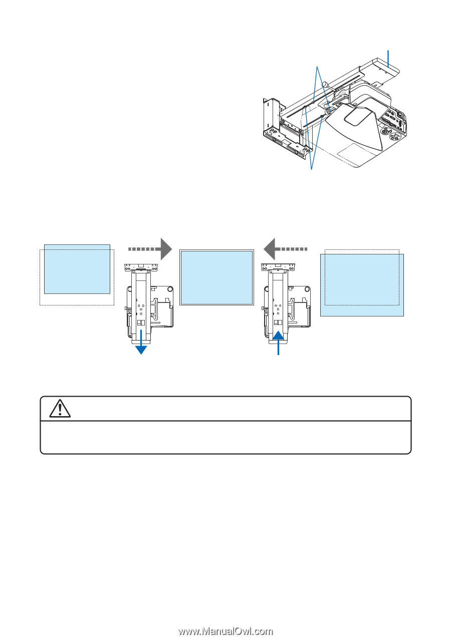
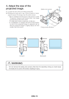
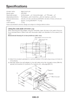
4. Adjust the size of the projected image. Cap Safety lock screws (1) Loosen the arm unit's two fixing screws (B). (2) Holding the slide arm's cap, move forward or back- ward to project the image over the entire screen. - When installed following the instructions under "Projection Distance and Screen Size", the image is projected at about the center. - The slide arm moves a maximum of 422 mm. - In consideration of change over time of the position to which the projected image is adjusted, set so that the projected image is slightly (about 20 mm) smaller than the screen. Fixing screws (B) (two) Forward Backward WARNING - Do not remove the safety lock screws other than for assembly. Doing so could cause the slide arm to come off and fall, resulting in injury. ENG-16
-
 1
1 -
2
-
3
-
4
-
5
-
6
-
7
-
8
-
9
-
10
-
11
-
 12
12 -
 13
13 -
 14
14 -
 15
15 -
 16
16 -
 17
17 -
 18
18 -
 19
19 -
 20
20 -
 21
21
 |
 |