Netgear GSM7328Sv2 GSM7328Sv2/GSM7352Sv2 Series Managed Switch Hardware Instal
Netgear GSM7328Sv2 - ProSafe 24+4 Gigabit Ethernet L3 Managed Stackable Switch Manual
 |
View all Netgear GSM7328Sv2 manuals
Add to My Manuals
Save this manual to your list of manuals |
Netgear GSM7328Sv2 manual content summary:
- Netgear GSM7328Sv2 | GSM7328Sv2/GSM7352Sv2 Series Managed Switch Hardware Instal - Page 1
Managed Stackable Layer 3 Switches GSM7328S v2 and GSM7352S v2 Hardware Installation Guide NETGEAR, Inc. 350 East Plumaria Drive Sant Jose, CA 95134 USA 202-10532-01 July 2009 - Netgear GSM7328Sv2 | GSM7328Sv2/GSM7352Sv2 Series Managed Switch Hardware Instal - Page 2
) in accordance with the regulations may, however, be subject to certain restrictions. Please refer to the notes in the operating instructions. It is hereby certified that the NETGEAR ProSafe™ 48-Port 10/100/1000 + 2-Port 10G L3 managed Stackable Switch with 2 10/12 Gigabit I/O Slots GSM7352S v2 has - Netgear GSM7328Sv2 | GSM7328Sv2/GSM7352Sv2 Series Managed Switch Hardware Instal - Page 3
and GSM7352S v2 Hardware Installation used in accordance with the instructions, may cause harmful interference to radio communications. However, 022 Class A (CISPR 22) and EN 55 024. This is to certify that the NETGEAR ProSafe™ 48-Port 10/100/1000 + 2-Port 10G L3 managed Stackable Switch with 2 10 - Netgear GSM7328Sv2 | GSM7328Sv2/GSM7352Sv2 Series Managed Switch Hardware Instal - Page 4
, in which case the user may be required to take appropriate measures. Customer Support Refer to the Support Information Card that shipped with your Managed Stackable Layer 3 Fast Ethernet Switch. World Wide Web NETGEAR maintains a World Wide Web home page that you can access at the universal - Netgear GSM7328Sv2 | GSM7328Sv2/GSM7352Sv2 Series Managed Switch Hardware Instal - Page 5
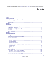
and Scope 1-1 How to Print this Manual 1-2 Revision History ...1-3 Chapter 2 Introduction GSM7328S v2 Front Panel and LEDs 2-1 GSM7328S v2 Rear Panel 2-4 GSM7352S v2 Front Panel and LEDs 2-4 GSM7352S v2 Rear Panel 2-7 Safety Instructions ...2-7 Chapter 3 Hardware Installation Package Contents - Netgear GSM7328Sv2 | GSM7328Sv2/GSM7352Sv2 Series Managed Switch Hardware Instal - Page 6
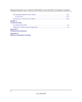
Connecting Equipment to the Switch 3-12 RJ-45 Ports ...3-12 Connecting a Console to the Switch 3-13 Chapter 4 Troubleshooting Troubleshooting Chart 4-1 Additional Troubleshooting Suggestions 4-2 Appendix A Technical Specifications Appendix B Default Configuration Settings vi v1.0, July 2009 - Netgear GSM7328Sv2 | GSM7328Sv2/GSM7352Sv2 Series Managed Switch Hardware Instal - Page 7
Conventions Italics Bold Fixed Emphasis, books, CDs, URL names User input Screen text, file and server names, extensions, commands, IP addresses This guide uses the following formats to highlight special messages: Note: This format is used to highlight information of importance or special - Netgear GSM7328Sv2 | GSM7328Sv2/GSM7352Sv2 Series Managed Switch Hardware Instal - Page 8
/ 12 Gigabit I/O Slots GSM7352S v2 July 2009 Note: Product updates are available on the NETGEAR, Inc. Web site at http://kbserver.netgear.com/downloads_support.asp. How to Print this Manual To print this manual, you can choose one of the following options, according to your needs. • Printing from - Netgear GSM7328Sv2 | GSM7328Sv2/GSM7352Sv2 Series Managed Switch Hardware Instal - Page 9
at the top left of any page in the manual. The PDF version of the complete manual opens in a browser window. • Click the print icon in the upper left of your browser window. Tip: If your printer supports printing two pages on a single sheet of paper, you can save paper and printer ink - Netgear GSM7328Sv2 | GSM7328Sv2/GSM7352Sv2 Series Managed Switch Hardware Instal - Page 10
Managed Stackable Layer 3 Switches GSM7328S v2 and GSM7352S v2 Hardware Installation 1-4 About This Manual v1.0, July 2009 - Netgear GSM7328Sv2 | GSM7328Sv2/GSM7352Sv2 Series Managed Switch Hardware Instal - Page 11
. This guide describes hardware installation and basic troubleshooting for the following NETGEAR switches: support any combination of either the ProSafe 24-Gigabit Stackable Module (AX742), the ProSafe 10-Gigabit Ethernet XFP Adapter (AX741) or the ProSafe 10-Gigabit Ethernet SFP+ Adapter - Netgear GSM7328Sv2 | GSM7328Sv2/GSM7352Sv2 Series Managed Switch Hardware Instal - Page 12
present and link up with system. • Blinking green: Packets transmission or reception is occurring on the port Stacking Adapter Link/ACT LED • Off: Stacking module is not present . • Solid green: Stacking module is present and link up with system. • Blinking green: Packets transmission or - Netgear GSM7328Sv2 | GSM7328Sv2/GSM7352Sv2 Series Managed Switch Hardware Instal - Page 13
Managed Stackable Layer 3 Switches GSM7328S v2 and GSM7352S v2 Hardware Installation Table 2-1. LED Descriptions for GSM7328S v2 (continued) LED Description 10/100/1000M Ports (2 LEDs per port) SFP Ports (1Link/ACT LED per port) SFP+ Ports (1 Link/ACT LED per port) Link/ACT LED • Off: No link - Netgear GSM7328Sv2 | GSM7328Sv2/GSM7352Sv2 Series Managed Switch Hardware Instal - Page 14
redundant power supply connector, and a power module for the supplied power cord. The module bays support any combination of the ProSafe 10-Gigabit Ethernet XFP Adapter (AX741), SFP+ Adapter (AX743), or the ProSafe 24Gigabit Stackable Module (AX742). Console Stacking/XFP module bays Power supply - Netgear GSM7328Sv2 | GSM7328Sv2/GSM7352Sv2 Series Managed Switch Hardware Instal - Page 15
Managed Stackable Layer 3 Switches GSM7328S v2 and GSM7352S v2 Hardware Installation The table below describes the GSM7352S v2 LEDs on the front of the switch. Table 2-2. GSM7352S v2 LED Description LED Description ID This is the stack member ID (1-8) that the software assigns to the switch. - Netgear GSM7328Sv2 | GSM7328Sv2/GSM7352Sv2 Series Managed Switch Hardware Instal - Page 16
is present and link up with system. • Blinking green: Packets transmission or reception is occurring on the port. Stacking Adapter Link/ACT LED • Off: Stacking module is not present or present but link down wih system. • Solid green: Stacking module is present and link up - Netgear GSM7328Sv2 | GSM7328Sv2/GSM7352Sv2 Series Managed Switch Hardware Instal - Page 17
module bays support any combination of the ProSafe 10-Gigabit Ethernet XFP Adapter (AX741), XFP+ Adapter (AX743), or the ProSafe 24-Gigabit Stackable Module (AX742). See "SFP+ Modules" in Chapter 3. Power receptacle Console Figure 2-4 Stacking/XFP module bays Safety Instructions Redundant power - Netgear GSM7328Sv2 | GSM7328Sv2/GSM7352Sv2 Series Managed Switch Hardware Instal - Page 18
the system gets wet, see the appropriate section in your troubleshooting guide or contact your trained service provider. • Do not push any objects into the openings with three-prong plugs to help ensure proper grounding. Do not use adapter plugs or remove the grounding prong from a cable. If you must - Netgear GSM7328Sv2 | GSM7328Sv2/GSM7352Sv2 Series Managed Switch Hardware Instal - Page 19
Managed Stackable Layer 3 Switches GSM7328S v2 and GSM7352S v2 Hardware Installation • Observe extension cable and power strip ratings. Make sure that the total ampere rating of all products plugged into the extension cable or power strip does not exceed 80 percent of the ampere ratings limit for - Netgear GSM7328Sv2 | GSM7328Sv2/GSM7352Sv2 Series Managed Switch Hardware Instal - Page 20
Managed Stackable Layer 3 Switches GSM7328S v2 and GSM7352S v2 Hardware Installation 2-10 v1.0, July 2009 Introduction - Netgear GSM7328Sv2 | GSM7328Sv2/GSM7352Sv2 Series Managed Switch Hardware Instal - Page 21
7300S Managed Switch CLI Manual, Version 8.0 , the NETGEAR 7000 Series Managed Switch Administration Guide, the NETGEAR Installation Guide for the 7000 Series Stackable Managed Switch, and this Hardware Installation Guide • Warranty Information and Technical Support card • ProSafe NMS100 Network - Netgear GSM7328Sv2 | GSM7328Sv2/GSM7352Sv2 Series Managed Switch Hardware Instal - Page 22
sure that all items are present. See "Package Contents" on page 3-1. Note: If any item is found missing or damaged, contact your local NETGEAR reseller for replacement. 5. Inspect the products and accessories for damage. Report any damage immediately. 3-2 Hardware Installation v1.0, July 2009 - Netgear GSM7328Sv2 | GSM7328Sv2/GSM7352Sv2 Series Managed Switch Hardware Instal - Page 23
Managed Stackable Layer 3 Switches GSM7328S v2 and GSM7352S v2 Hardware Installation Installation Install the equipment in the sequence presented in this chapter, as shown below: 1. Select a Location. See "Select a Location" on page 3-4. 2. Install the Switch. See "Install the Switch" on page 3-5. - Netgear GSM7328Sv2 | GSM7328Sv2/GSM7352Sv2 Series Managed Switch Hardware Instal - Page 24
Managed Stackable Layer 3 Switches GSM7328S v2 and GSM7352S v2 Hardware Installation Select a Location The switch can be mounted in a standard 19-inch (48.26-centimeter) rack, wall-mounted, or left freestanding (placed on a tabletop). The site where you install the switch may greatly affect its - Netgear GSM7328Sv2 | GSM7328Sv2/GSM7352Sv2 Series Managed Switch Hardware Instal - Page 25
Managed Stackable Layer 3 Switches GSM7328S v2 and GSM7352S v2 Hardware Installation Install the Switch You can install the switch on a flat surface or in a standard 19-inch rack. Installing the Switch on a Flat Surface The switch ships with four self-adhesive rubber footpads. Stick one rubber - Netgear GSM7328Sv2 | GSM7328Sv2/GSM7352Sv2 Series Managed Switch Hardware Instal - Page 26
these steps to apply AC power. 1. Connect one end of the AC power adapter cable to the rear of the switch, and the other end to a grounded and that the power source is good. For help with troubleshooting, see Chapter 4, "Troubleshooting. SFP+ Modules The module bay accommodates a standard SFP+ - Netgear GSM7328Sv2 | GSM7328Sv2/GSM7352Sv2 Series Managed Switch Hardware Instal - Page 27
Ethernet modules, repeat step 1. High-Speed I/O Module Bays The High-Speed I/O Module Bays support ProSafe 10-Gigabit Ethernet XFP Adapters (AX741), ProSafe 10-Gigabit Ethernet SFP+ Adapters (AX743), or ProSafe 24-Gigabit Stackable Modules (AX742). Hardware Installation 3-7 v1.0, July 2009 - Netgear GSM7328Sv2 | GSM7328Sv2/GSM7352Sv2 Series Managed Switch Hardware Instal - Page 28
bays for 10-Gigabit Ethernet XFP Adapters (AX741) or 10-Gigabit Ethernet SFP+ Adapters (AX743). The modules and adapters are sold seperately. AX741 adapter Figure 3-3 When the ProSafe 10-Gigabit Ethernet XFP Adapter (AX741) or ProSafe 10-Gigabit Ethernet SFP+ Adapter (AX743) is in place, you can - Netgear GSM7328Sv2 | GSM7328Sv2/GSM7352Sv2 Series Managed Switch Hardware Instal - Page 29
, as explained in the next section, "Stacking" on page 3-9. Stacking You can connect up to eight switches to form a stack with a single management IP address. The switches automatically select a master unit. Once the master is selected, you can use its console to manage all the switches in the stack - Netgear GSM7328Sv2 | GSM7328Sv2/GSM7352Sv2 Series Managed Switch Hardware Instal - Page 30
, and gently push the module into the slot. 2. Align the two captive screws with the screw holes in the switch's rear panel. 3. Using a screw driver, gently tighten the captive screws. 4. Connect the power cord to the module and to an AC-powered outlet. Removing a Power Module (APS135W) To remove - Netgear GSM7328Sv2 | GSM7328Sv2/GSM7352Sv2 Series Managed Switch Hardware Instal - Page 31
Managed Stackable Layer 3 Switches GSM7328S v2 and GSM7352S v2 Hardware Installation Connecting a Redundant Power Supply Each switch has a redundant power supply (RPS) connector at the rear of the switch next to the power supply panel. Power receptacle Figure 3-6 Redundant power supply connector - Netgear GSM7328Sv2 | GSM7328Sv2/GSM7352Sv2 Series Managed Switch Hardware Instal - Page 32
the switch and apply power, you can connect to it with a terminal or workstation. You can use the Command Line Interface (CLI) to identify the IP address. If you are stacking switches, see "Stacking" on page 3-9. To use a console you need the following items: • VT100/ANSI terminal, or a Windows PC - Netgear GSM7328Sv2 | GSM7328Sv2/GSM7352Sv2 Series Managed Switch Hardware Instal - Page 33
following documents are provided for this purpose: • Quick Installation Guide: Explains basic setup and configuration (provided as both a print document and in is located on the Resource CD. • NETGEAR 7000 Series Managed Switch Administration Guide: Describes configuration tasks, and is located on - Netgear GSM7328Sv2 | GSM7328Sv2/GSM7352Sv2 Series Managed Switch Hardware Instal - Page 34
Managed Stackable Layer 3 Switches GSM7328S v2 and GSM7352S v2 Hardware Installation 3-14 v1.0, July 2009 Hardware Installation - Netgear GSM7328Sv2 | GSM7328Sv2/GSM7352Sv2 Series Managed Switch Hardware Instal - Page 35
lists symptoms, causes, and solutions of possible problems. Table 4-1. Troubleshooting Chart Problem Power LED is off. Link LED is off and comply with Ethernet specifications. See Appendix A. Check for a defective adapter card, cable, or port by testing it in an alternate environment where - Netgear GSM7328Sv2 | GSM7328Sv2/GSM7352Sv2 Series Managed Switch Hardware Instal - Page 36
4-1 do not resolve your problem, refer to the troubleshooting suggestions in this section. • Network Adapter Cards Make sure that the network adapter cards installed in the PCs are in working condition and the software driver has been installed. • Configuration: If problems occur after you change - Netgear GSM7328Sv2 | GSM7328Sv2/GSM7352Sv2 Series Managed Switch Hardware Instal - Page 37
3z 1000BASE-LX 802.3ab 1000BASE-T 802.3ae 10000BASE-LR 802.3ae 10000BASE-SR 802.3x flow control Switch management • Port mirroring support • SNMP v1, v2c, v3 • RFC1757 RMON 1 groups 1, 2, 3, and 9 • RFC1213 MIB II • RFC1643 Ethernet Interface MIB • RFC1493 bridge MIB • RFC2131 DHCP client (and - Netgear GSM7328Sv2 | GSM7328Sv2/GSM7352Sv2 Series Managed Switch Hardware Instal - Page 38
(MSTP) • 802.3ad Link Aggregation (LACP) • IGMP v1, v2 Snooping Support • MLD snooping Layer 3 Services • VLAN routing • Port routing • RIP v1, v2 • OSPF v2, 184 Gbps Address database size 8K MAC addresses per system 10/100/1000 buffer memory Max support 0.75-MB buffer memory Max support 1.5-MB - Netgear GSM7328Sv2 | GSM7328Sv2/GSM7352Sv2 Series Managed Switch Hardware Instal - Page 39
• Network latency: Less than 80 microseconds for 64-byte frames in store-and- forward mode for 10 Mbps to 100 Mbps transmission • Addressing: 48-bit MAC address • Acoustic noise: (ANSI-S10.12): 44 dB @ 25°C ambient temperature • Heat dissipation: 260.488 Btu/hr for the GSM7328Sv2, 389.196 Btu - Netgear GSM7328Sv2 | GSM7328Sv2/GSM7352Sv2 Series Managed Switch Hardware Instal - Page 40
Managed Stackable Layer 3 Switches GSM7328S v2 and GSM7352S v2 Hardware Installation A-4 Technical Specifications v1.0, July 2009 - Netgear GSM7328Sv2 | GSM7328Sv2/GSM7352Sv2 Series Managed Switch Hardware Instal - Page 41
Configuration Settings This appendix provides the default settings for the NETGEAR Model GSM7328S v2 and GSM7352S v2. Table B-1. Default port Link aggregation Port mirroring Traffic prioritization ACL GVRP GMRP IP routing Auto-negotiation Auto-negotiation Enabled Disabled Enabled Auto detect DHCP - Netgear GSM7328Sv2 | GSM7328Sv2/GSM7352Sv2 Series Managed Switch Hardware Instal - Page 42
Layer 3 Switches GSM7328S v2 and GSM7352S v2 Hardware Installation Table B-1. Default Configuration Settings (continued) Features RIP MAC address aging OSPF SNMP community DHCP Server VLAN Ingress filtering IP multicast filtering VRRP IGMP DVMRP PIM-SM PIM-DM IPv6 routing PIM-SM(IPv6) PIM-DM(IPv6
-
 1
1 -
 2
2 -
 3
3 -
 4
4 -
 5
5 -
 6
6 -
 7
7 -
8
-
9
-
10
-
11
-
12
-
13
-
14
-
15
-
16
-
17
-
18
-
19
-
20
-
21
-
22
-
23
-
24
-
25
-
26
-
27
-
28
-
29
-
30
-
31
-
32
-
33
-
34
-
35
-
36
-
37
-
38
-
39
-
40
-
41
-
42
 |
 |

202-10532-01
July 2009
NETGEAR
, Inc.
350 East Plumaria Drive
Sant Jose, CA 95134 USA
Managed Stackable Layer
3 Switches GSM7328S v2
and GSM7352S v2
Hardware Installation
Guide