Netgear GSM7328Sv2 GSM7328Sv2/GSM7352Sv2 Series Managed Switch Hardware Instal - Page 12
Table, LED Descriptions for GSM7328S v2
 |
View all Netgear GSM7328Sv2 manuals
Add to My Manuals
Save this manual to your list of manuals |
Page 12 highlights
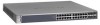
Managed Stackable Layer 3 Switches GSM7328S v2 and GSM7352S v2 Hardware Installation The following table describes the LEDs on the front panel of the switch. Table 2-1. LED Descriptions for GSM7328S v2 LED Description ID This is the stack member ID (1-8) that the software assigns to the switch. Master • Green: Switch acts as a master unit in a stack of GSM7300S series switches. • Off: Switch acts as a slave unit in a stack of GSM7300S switches. RPS (redundant power supply) • Solid green: The redundant power supply is connected (and using the power module's power). • Solid yellow: The power module power has failed or been disconnected, but the redundant power supply is providing power to the switch. • Blinking yellow: The redundant power supply unit is present, but the power has failed. • Off: The redundant power supply is disconnected or not present. Fan • Solid green: Fan operating normally. • Solid yellow: Fan has failed • Off: No fan detected. PWR (power) • Solid green: Power module is present and supplys power to the switch and is working normally. • Solid yellow: System is in boot-up stage. • Blinking yellow: POS/CPU system has failed. • Off: Power is disconnected. M1, M2 High-Speed I/O Modules (1 LED per module) XFP Module present or Stacking Adapter present and ACT LED: XFP Module present LED /ACT • Off: The 10GbE Adapter is not present or present but link down with system. • Solid green: The 10GbE Adapter is present and link up with system. • Blinking green: Packets transmission or reception is occurring on the port Stacking Adapter Link/ACT LED • Off: Stacking module is not present . • Solid green: Stacking module is present and link up with system. • Blinking green: Packets transmission or reception is occurring on the port . 2-2 Introduction v1.0, July 2009
-
 1
1 -
2
-
3
-
4
-
5
-
6
-
 7
7 -
 8
8 -
 9
9 -
 10
10 -
 11
11 -
 12
12 -
 13
13 -
 14
14 -
 15
15 -
 16
16 -
 17
17 -
18
-
19
-
20
-
21
-
22
-
23
-
24
-
25
-
26
-
27
-
28
-
29
-
30
-
31
-
32
-
33
-
34
-
35
-
36
-
37
-
38
-
39
-
40
-
41
-
42
 |
 |
