Netgear GSM7328Sv2 GSM7328Sv2/GSM7352Sv2 Series Managed Switch Hardware Instal - Page 31
Connecting a Redundant Power Supply, Connecting Equipment to the Switch, RJ-45 Ports
 |
View all Netgear GSM7328Sv2 manuals
Add to My Manuals
Save this manual to your list of manuals |
Page 31 highlights
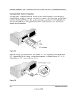
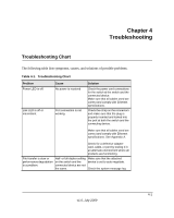
Managed Stackable Layer 3 Switches GSM7328S v2 and GSM7352S v2 Hardware Installation Connecting a Redundant Power Supply Each switch has a redundant power supply (RPS) connector at the rear of the switch next to the power supply panel. Power receptacle Figure 3-6 Redundant power supply connector You can connect an external DC-to-DC power supply unit to the switch to provide redundant power in case the primary power supply fails. To connect a redundant power supply (RPS) unit to the switch, first turn off the switch. When the power is off, you can remove the cover plate and connect the RPS unit to the switch. After all connections are completed, apply power to the switch. Connecting Equipment to the Switch You can connect devices, a Gigabit Ethernet module, and/or a console to the switch. RJ-45 Ports The switch uses Auto Uplink technology, which enables you to attach devices using either straight-through or crossover cables. Use a Category 5 (Cat5) unshielded twisted-pair (UTP) cable terminated with an RJ-45 connector. Note: Ethernet specifications limit the cable length between the switch and the attached device to 328 feet (100 meters). Hardware Installation v1.0, July 2009 3-11
-
 1
1 -
2
-
3
-
4
-
5
-
6
-
7
-
8
-
9
-
10
-
11
-
12
-
13
-
14
-
15
-
16
-
17
-
18
-
19
-
20
-
21
-
22
-
23
-
24
-
25
-
 26
26 -
 27
27 -
 28
28 -
 29
29 -
 30
30 -
 31
31 -
 32
32 -
 33
33 -
 34
34 -
 35
35 -
 36
36 -
37
-
38
-
39
-
40
-
41
-
42
 |
 |
