Managed Stackable Layer 3 Switches GSM7328S v2 and GSM7352S v2 Hardware Installation
v
v1.0, July 2009
Contents
Chapter
1
About This Manual
Audience, Conventions, Formats, and Scope
................................................................
1-1
How to Print this Manual
.................................................................................................
1-2
Revision History
..............................................................................................................
1-3
Chapter
2
Introduction
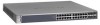
GSM7328S v2 Front Panel and LEDs
............................................................................
2-1
GSM7328S v2 Rear Panel
.............................................................................................
2-4
GSM7352S v2 Front Panel and LEDs
............................................................................
2-4
GSM7352S v2 Rear Panel
.............................................................................................
2-7
Safety Instructions
..........................................................................................................
2-7
Chapter
3
Hardware Installation
Package Contents
..........................................................................................................
3-1
Protecting Against Electrostatic Discharge
.....................................................................
3-2
Unpacking the Hardware
................................................................................................
3-2
Installation
......................................................................................................................
3-3
Select a Location
......................................................................................................
3-4
Install the Switch
......................................................................................................
3-5
Check the Installation
...............................................................................................
3-6
Connect to Power and Check the LEDs
...................................................................
3-6
SFP+ Modules
.........................................................................................................
3-7
SFP Modules
............................................................................................................
3-7
Stacking
...................................................................................................................
3-9
Power Module Bay
.......................................................................................................
3-10
Installing a Power Module (APS135W)
..................................................................
3-11
Removing a Power Module (APS135W)
................................................................
3-11
Connecting a Redundant Power Supply
.......................................................................
3-12
 1
1 2
2 3
3 4
4 5
5 6
6 7
7 8
8 9
9 10
10 11
11

