Panasonic 26PEK1U6 Tech Data - Service Manual
Panasonic 26PEK1U6 Manual
 |
View all Panasonic 26PEK1U6 manuals
Add to My Manuals
Save this manual to your list of manuals |
Panasonic 26PEK1U6 manual content summary:
- Panasonic 26PEK1U6 | Tech Data - Service Manual - Page 1
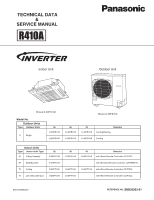
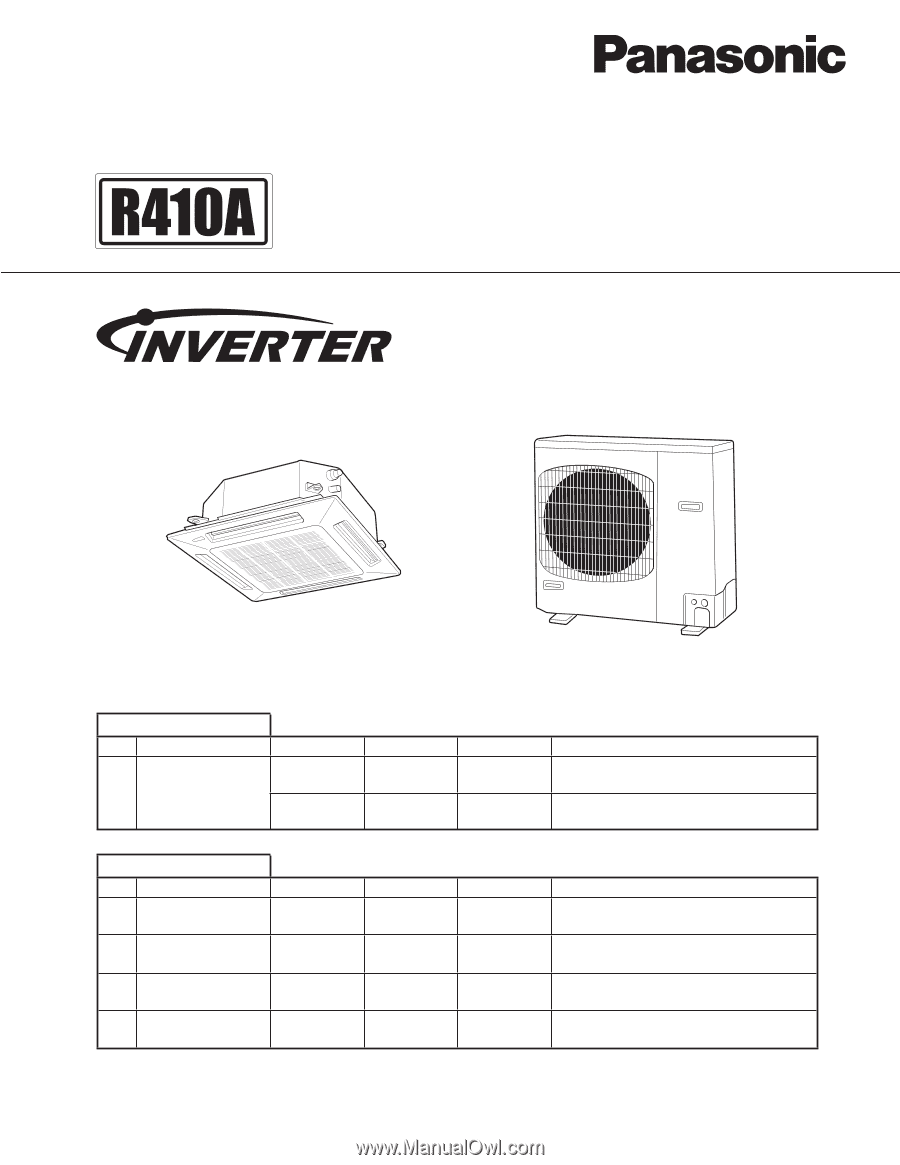
TECHNICAL DATA & SERVICE MANUAL Indoor Unit Outdoor Unit Shows S-26PU1U6 Model No. Outdoor Units Type Outdoor Units U Single 26 U-26PE1U6 U-26PS1U6 36 U-36PE1U6 U-36PS1U6 Shows U-26PE1U6 42 U-42PE1U6 Remarks - Panasonic 26PEK1U6 | Tech Data - Service Manual - Page 2
trouble-free operation, you must: thin aluminum fins on the air conditioner can cut your Carefully read this instruction problem, contact our sales/service outlet or your certified dealer for additional instructions. Select an installation location which is rigid and strong enough to support - Panasonic 26PEK1U6 | Tech Data - Service Manual - Page 3
no metal scraps or bits of wiring have been left inside the unit being serviced. WARNING • Do not clean inside the indoor and outdoor units by users. Caution: To assure continued compliance, follow the attached installation instructions. Any changes or modifications not expressly approved by the - Panasonic 26PEK1U6 | Tech Data - Service Manual - Page 4
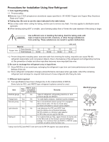
Precautions for Installation Using New Refrigerant 1. Care regarding tubing 1-1. Process tubing Material: Use C1220 phosphorous deoxidized copper specified in JIS H3300 "Copper and Copper Alloy Seamless Pipes and Tubes." Tubing size: Be sure to use the sizes indicated in the table below. Use a tube - Panasonic 26PEK1U6 | Tech Data - Service Manual - Page 5
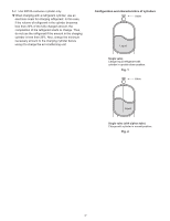
3-2. Use R410A exclusive cylinder only. When charging with a refrigerant cylinder, use an electronic scale for charging refrigerant. In this case, if the volume of refrigerant in the cylinder becomes less than 20% of the fully-charged amount, the composition of the refrigerant starts to change. Thus - Panasonic 26PEK1U6 | Tech Data - Service Manual - Page 6
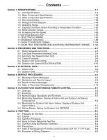
throw distance chart 1-57 1-11 ELECTRICAL WIRING 1-60 1-12 Installation Instructions 1-63 1-13 HOW TO PROCESS TUBING 1-118 1-14 LEAK TEST, DATA 3-1 3-1 Indoor Units ...3-2 3-2 Outdoor Units...3-10 Section 4: SERVICE PROCEDURES 4-1 4-1 Meaning of Alarm Messages 4-2 4-2 Symptoms and Parts to - Panasonic 26PEK1U6 | Tech Data - Service Manual - Page 7
Curves 1-51 1-9. Increasing the Fan Speed 1-56 1-10. Air throw distance chart 1-57 1-11. ELECTRICAL WIRING 1-60 1-12. Installation Instructions 1-63 1 Outdoor Unit 1. Tubing Size ...1-63 2. Check of density limit ...1-64 3. SELECTING THE INSTALLATION SITE 1-65 4. HOW TO INSTALL - Panasonic 26PEK1U6 | Tech Data - Service Manual - Page 8
1-1 Unit Specifications 1. Specifications 4-Way Cassette Type MODEL No. Indoor Unit S-26PU1U6 Outdoor Unit U-26PE1U6 POWER SOURCE 230 - 208 V / 1 Phase / 60 Hz PERFORMANCE Cooling Heating Capacity * [minimum~muximum] BTU / h 24,800 [9,500~24,800] 29,800 [8,000~29,800] (17˚F)** BTU / - Panasonic 26PEK1U6 | Tech Data - Service Manual - Page 9
1-1 Unit Specifications 1. Specifications 4-Way Cassette Type MODEL No. Indoor Unit S-36PU1U6 Outdoor Unit U-36PE1U6 POWER SOURCE 230 - 208 V / 1 Phase / 60 Hz PERFORMANCE Cooling Heating Capacity * [minimum~muximum] BTU / h 32,600 [9,500~32,600] 37,600 [8,000~37,600] (17˚F)** BTU / - Panasonic 26PEK1U6 | Tech Data - Service Manual - Page 10
1-1 Unit Specifications 1. Specifications 4-Way Cassette Type MODEL No. Indoor Unit S-42PU1U6 Outdoor Unit U-42PE1U6 POWER SOURCE 230 - 208 V / 1 Phase / 60 Hz PERFORMANCE Cooling Heating Capacity * [minimum~muximum] BTU / h 39,500 [9,500~39,500] 48,000 [8,000~48,000] (17˚F)** BTU / - Panasonic 26PEK1U6 | Tech Data - Service Manual - Page 11
1-1 Unit Specifications 1. Specifications 4-Way Cassette Type MODEL No. Indoor Unit S-26PU1U6 Outdoor Unit U-26PS1U6 POWER SOURCE 230 - 208 V / 1 Phase / 60 Hz PERFORMANCE Cooling Capacity * [minimum~muximum] BTU / h 24,800 [9,500~24,800] (17˚F)** BTU / h Moisture removal (High) - Panasonic 26PEK1U6 | Tech Data - Service Manual - Page 12
1-1 Unit Specifications 1. Specifications 4-Way Cassette Type MODEL No. Indoor Unit S-36PU1U6 Outdoor Unit U-36PS1U6 POWER SOURCE 230 - 208 V / 1 Phase / 60 Hz PERFORMANCE Cooling Capacity * [minimum~muximum] BTU / h 32,600 [9,500~32,600] (17˚F)** BTU / h Moisture removal (High) - Panasonic 26PEK1U6 | Tech Data - Service Manual - Page 13
1-1 Unit Specifications 1. Specifications 4-Way Cassette Type MODEL No. Indoor Unit S-42PU1U6 Outdoor Unit U-42PS1U6 POWER SOURCE 230 - 208 V / 1 Phase / 60 Hz PERFORMANCE Cooling Capacity * [minimum~muximum] BTU / h 39,500 [9,500~39,500] (17˚F)** BTU / h Moisture removal (High) - Panasonic 26PEK1U6 | Tech Data - Service Manual - Page 14
1-1 Unit Specifications 1. Specifications Wall Mounted Type MODEL No. Indoor Unit S-26PK1U6 Outdoor Unit U-26PE1U6 POWER SOURCE 230 - 208 V / 1 Phase / 60 Hz PERFORMANCE Cooling Heating Capacity * [minimum~muximum] BTU / h 25,200 [9,500~25,200] 29,200 [8,000~29,200] (17˚F)** BTU / h - Panasonic 26PEK1U6 | Tech Data - Service Manual - Page 15
1-1 Unit Specifications 1. Specifications Wall Mounted Type MODEL No. Indoor Unit S-26PK1U6 Outdoor Unit U-26PS1U6 POWER SOURCE 230 - 208 V / 1 Phase / 60 Hz PERFORMANCE Cooling Capacity * [minimum~muximum] BTU / h 25,200 [9,500~25,200] (17˚F)** BTU / h Moisture removal (High) - Panasonic 26PEK1U6 | Tech Data - Service Manual - Page 16
1-1 Unit Specifications 1. Specifications Ceiling Type MODEL No. Indoor Unit S-26PT1U6 Outdoor Unit U-26PE1U6 POWER SOURCE 230 - 208 V / 1 Phase / 60 Hz PERFORMANCE Cooling Heating Capacity * [minimum~muximum] (17˚F)** Moisture removal (High) BTU / h 24,400 [9,500~24,400] BTU / h - Panasonic 26PEK1U6 | Tech Data - Service Manual - Page 17
1-1 Unit Specifications 1. Specifications Ceiling Type MODEL No. Indoor Unit S-36PT1U6 Outdoor Unit U-36PE1U6 POWER SOURCE 230 - 208 V / 1 Phase / 60 Hz PERFORMANCE Cooling Heating Capacity * [minimum~muximum] (17˚F)** Moisture removal (High) BTU / h 31,200 [9,500~31,200] BTU / h - Panasonic 26PEK1U6 | Tech Data - Service Manual - Page 18
1-1 Unit Specifications 1. Specifications Ceiling Type MODEL No. Indoor Unit S-42PT1U6 Outdoor Unit U-42PE1U6 POWER SOURCE 230 - 208 V / 1 Phase / 60 Hz PERFORMANCE Cooling Heating Capacity * [minimum~muximum] (17˚F)** Moisture removal (High) BTU / h 39,000 [9,500~39,000] BTU / h - Panasonic 26PEK1U6 | Tech Data - Service Manual - Page 19
1-1 Unit Specifications 1. Specifications Ceiling Type MODEL No. Indoor Unit S-26PT1U6 Outdoor Unit U-26PS1U6 POWER SOURCE 230 - 208 V / 1 Phase / 60 Hz PERFORMANCE Cooling Capacity * [minimum~muximum] (17˚F)** Moisture removal (High) BTU / h BTU / h Pints / h 24,400 [9,500~24,400] 7.7 - Panasonic 26PEK1U6 | Tech Data - Service Manual - Page 20
1-1 Unit Specifications 1. Specifications Ceiling Type MODEL No. Indoor Unit S-36PT1U6 Outdoor Unit U-36PS1U6 POWER SOURCE 230 - 208 V / 1 Phase / 60 Hz PERFORMANCE Cooling Capacity * [minimum~muximum] (17˚F)** Moisture removal (High) BTU / h BTU / h Pints / h 31,200 [9,500~31,200] 10 - Panasonic 26PEK1U6 | Tech Data - Service Manual - Page 21
1-1 Unit Specifications 1. Specifications Ceiling Type MODEL No. Indoor Unit S-42PT1U6 Outdoor Unit U-42PS1U6 POWER SOURCE 230 - 208 V / 1 Phase / 60 Hz PERFORMANCE Cooling Capacity * [minimum~muximum] (17˚F)** Moisture removal (High) BTU / h BTU / h Pints / h 39,000 [9,500~39,000] 12 - Panasonic 26PEK1U6 | Tech Data - Service Manual - Page 22
1-1 Unit Specifications 1. Specifications Low Silhouette Duct Type MODEL No. Indoor Unit S-26PF1U6 Outdoor Unit U-26PE1U6 POWER SOURCE 230 - 208 V / 1 Phase / 60 Hz PERFORMANCE Cooling Heating Capacity * [minimum~muximum] BTU / h 24,000 [9,500~24,000] 28,600 [8,000~28,600] (17˚F)** - Panasonic 26PEK1U6 | Tech Data - Service Manual - Page 23
1-1 Unit Specifications 1. Specifications Low Silhouette Duct Type MODEL No. Indoor Unit S-36PF1U6 Outdoor Unit U-36PE1U6 POWER SOURCE 230 - 208 V / 1 Phase / 60 Hz PERFORMANCE Cooling Heating Capacity * [minimum~muximum] BTU / h 31,200 [9,500~31,200] 36,200 [8,000~36,200] (17˚F)** - Panasonic 26PEK1U6 | Tech Data - Service Manual - Page 24
1-1 Unit Specifications 1. Specifications Low Silhouette Duct Type MODEL No. Indoor Unit S-26PF1U6 Outdoor Unit U-26PS1U6 POWER SOURCE 230 - 208 V / 1 Phase / 60 Hz PERFORMANCE Cooling Capacity * [minimum~muximum] BTU / h 24,000 [9,500~24,000] (17˚F)** BTU / h - Moisture removal ( - Panasonic 26PEK1U6 | Tech Data - Service Manual - Page 25
1-1 Unit Specifications 1. Specifications Low Silhouette Duct Type MODEL No. Indoor Unit S-36PF1U6 Outdoor Unit U-36PS1U6 POWER SOURCE 230 - 208 V / 1 Phase / 60 Hz PERFORMANCE Cooling Capacity * [minimum~muximum] BTU / h 31,200 [9,500~31,200] (17˚F)** BTU / h - Moisture removal ( - Panasonic 26PEK1U6 | Tech Data - Service Manual - Page 26
1-2 Major Component Specifications (A) Indoor Unit MODEL No. Source Remote controller (Supplied / Optional) Controller P. C. B Ass'y Control circuit fuse Fan (Number ... diameter) in. (mm) Fan motor Model Source No. of pole ... r.p.m. (230 V, High) rpm Nominal output W Coil - Panasonic 26PEK1U6 | Tech Data - Service Manual - Page 27
1-2 Major Component Specifications (A) Indoor Unit MODEL No. Source Remote controller (Supplied / Optional) Controller P. C. B Ass'y Control circuit fuse Fan (Number ... diameter) in. (mm) Fan motor Model Source No. of pole ... r.p.m. (230 V, High) rpm Nominal output W Coil - Panasonic 26PEK1U6 | Tech Data - Service Manual - Page 28
1-2 Major Component Specifications (A) Indoor Unit MODEL No. Source Remote controller (Supplied / Optional) Controller P. C. B Ass'y Control circuit fuse Fan (Number ... diameter) in. (mm) Fan motor Model Source No. of pole ... r.p.m. (230 V, High) rpm Nominal output W Coil - Panasonic 26PEK1U6 | Tech Data - Service Manual - Page 29
1-2 Major Component Specifications (A) Indoor Unit MODEL No. Source Remote controller (Optional / Supplied) Controller P. C. B Ass'y Control circuit fuse Fan Number ... Dia. and length Fan motor Model Source No. of pole ... r.p.m. (230 V, High) Nominal output Coil resistance (Ambient temperature - Panasonic 26PEK1U6 | Tech Data - Service Manual - Page 30
1-2 Major Component Specifications (A) Indoor Unit MODEL No. Source Remote controller (Supplied / Optional) Controller P. C. B Ass'y Control circuit fuse Fan (Number ... diameter) Fan motor Model Source No. of pole ... r.p.m. (230 V, High) Nominal output Coil resistance (Ambient temperature 68 °F) - Panasonic 26PEK1U6 | Tech Data - Service Manual - Page 31
1-2 Major Component Specifications (A) Indoor Unit MODEL No. Source Remote controller (Supplied / Optional) Controller P. C. B Ass'y Control circuit fuse Fan (Number ... diameter) Fan motor Model Source No. of pole ... r.p.m. (230 V, High) Nominal output Coil resistance (Ambient temperature 68 °F) - Panasonic 26PEK1U6 | Tech Data - Service Manual - Page 32
1-2 Major Component Specifications (A) Indoor Unit MODEL No. Source Remote controller (Supplied / Optional) Controller P. C. B Ass'y Control circuit fuse Fan (Number ... diameter) Fan motor Model Source No. of pole ... r.p.m. (230 V, High) Nominal output Coil resistance (Ambient temperature 68 °F) - Panasonic 26PEK1U6 | Tech Data - Service Manual - Page 33
1-2 Major Component Specifications (A) Indoor Unit MODEL No. Source Remote controller (Supplied / Optional) Controller P. C. B Ass'y Control circuit fuse Fan (Number ... diameter) Fan motor Model Source No. of pole ... r.p.m. (230 V, High) Nominal output Coil resistance (Ambient temperature 68 °F) - Panasonic 26PEK1U6 | Tech Data - Service Manual - Page 34
1-2 Major Component Specifications (A) Indoor Unit MODEL No. Source Remote controller (Supplied / Optional) Controller P. C. B Ass'y Control circuit fuse Fan (Number ... diameter) Fan motor Model Source No. of pole ... r.p.m. (230 V, High) Nominal output Coil resistance (Ambient temperature 68 °F) - Panasonic 26PEK1U6 | Tech Data - Service Manual - Page 35
1-2 Major Component Specifications (B) Outdoor Unit MODEL No. Source Controller P.C.B. Ass'y Control circuit fuse (on the P.C.B."FIL-CH4872R") Compressor Model....number Nominal output W Compressor oil cc Coil resistance Ω (Ambient temperature 25 °C) Safety control Microprocessor - Panasonic 26PEK1U6 | Tech Data - Service Manual - Page 36
1-2 Major Component Specifications (B) Outdoor Unit MODEL No. Source Controller P.C.B. Ass'y Control circuit fuse (on the P.C.B."FIL-CH4872R") Compressor Model....number Nominal output W Compressor oil cc Coil resistance Ω (Ambient temperature 25 °C) Safety control Microprocessor - Panasonic 26PEK1U6 | Tech Data - Service Manual - Page 37
1-2 Major Component Specifications (B) Outdoor Unit MODEL No. Source Controller P.C.B. Ass'y Control circuit fuse (on the P.C.B."FIL-CH4872R") Compressor Model....number Nominal output W Compressor oil cc Coil resistance Ω (Ambient temperature 25 °C) Safety control Microprocessor - Panasonic 26PEK1U6 | Tech Data - Service Manual - Page 38
1-2 Major Component Specifications (B) Outdoor Unit MODEL No. Source Controller P.C.B. Ass'y Control circuit fuse (on the P.C.B."FIL-CH4872R") Compressor Model....number Nominal output W Compressor oil cc Coil resistance Ω (Ambient temperature 25 °C) Safety control Microprocessor - Panasonic 26PEK1U6 | Tech Data - Service Manual - Page 39
1-2 Major Component Specifications (B) Outdoor Unit MODEL No. Source Controller P.C.B. Ass'y Control circuit fuse (on the P.C.B."FIL-CH4872R") Compressor Model....number Nominal output W Compressor oil cc Coil resistance Ω (Ambient temperature 25 °C) Safety control Microprocessor - Panasonic 26PEK1U6 | Tech Data - Service Manual - Page 40
1-2 Major Component Specifications (B) Outdoor Unit MODEL No. Source Controller P.C.B. Ass'y Control circuit fuse (on the P.C.B."FIL-CH4872R") Compressor Model....number Nominal output W Compressor oil cc Coil resistance Ω (Ambient temperature 25 °C) Safety control Microprocessor - Panasonic 26PEK1U6 | Tech Data - Service Manual - Page 41
1-3 Other Component Specifications 1. Specifications Outdoor Unit MODEL No. U-26PE1U6, U-26PS1U6 Thermistor (Coil sensor) : TH2 to 5 Coil resistance kΩ 14 °F : 23.7 , 50 °F : 9.7 23 °F : 18.8 , 68 °F : 6.5 32 °F : 15.0 , 86 °F : 4.4 41 °F : 12.1 , 104 °F : 3.1 113 °F : 2.6 - Panasonic 26PEK1U6 | Tech Data - Service Manual - Page 42
1-3 Other Component Specifications 1. Specifications Outdoor Unit MODEL No. Thermistor (Coil sensor) : TH2 to 5 Coil resistance kΩ Thermistor (Comp. discharge gas sensor) : TH6 Coil resistance kΩ Solenoid coil or 4 way valve 4 way valve Solenoid coil Electric expansion valve (MOV) 1 - Panasonic 26PEK1U6 | Tech Data - Service Manual - Page 43
1-3 Other Component Specifications 1. Specifications Outdoor Unit MODEL No. U-42PE1U6, U-42PS1U6 Thermistor (Coil sensor) : TH2 to 5 Coil resistance kΩ 14 °F : 23.7 , 50 °F : 9.7 23 °F : 18.8 , 68 °F : 6.5 32 °F : 15.0 , 86 °F : 4.4 41 °F : 12.1 , 104 °F : 3.1 113 °F : 2.6 - Panasonic 26PEK1U6 | Tech Data - Service Manual - Page 44
1-4 Dimensional data Indoor unit : 4-Way Cassette Type 26 Type 4-7/8 10-9/32 8-11/16 Min. 2-15/32 Min. 19/32 3 1. Specifications 3-15/16 13-11/32 X-view 11-1/2 9-1/8 4-7/8 2-5/16 6-3/16 1 7-5/32 32-9/32 (Ceiling opening) 29-13/16 (Suspention bolt pitch) 12-1/8 4-7/8 1-7/8 1-3/16 33- - Panasonic 26PEK1U6 | Tech Data - Service Manual - Page 45
1-4 Dimensional data Indoor unit : 4-Way Cassette Type 36, 42Type 4-7/8 11-15/32 9-19/32 13-11/32 3-15/16 1. Specifications Min. 2-15/32 Min. 19/32 3 X-view 11-1/2 9-1/8 2-5/16 6-3/16 4-7/8 7-5/32 32-9/32 (Ceiling opening) 13-5/16 1-3/16 33-27/32 1 29-13/16 (Suspention bolt pitch) - Panasonic 26PEK1U6 | Tech Data - Service Manual - Page 46
1-4 Dimensional data Indoor unit : Wall Mounted Type 1. Specifications Drain and wiring port (3-5/32) Refrigerant liquid line (3/8") Flare connection 1 Refrigerant gas line (5/8") Flare connection Drain hose OD 45/64 Dimension : inch 1-40 - Panasonic 26PEK1U6 | Tech Data - Service Manual - Page 47
(Suspension bolt hole pitch) 1-3/8 50-13/32 26-3/8 3-3/4 5-25/32 7-15/32 9-7/8 Air intake 10 Air outlet or more (Service space) 51-3/16 Front 10 or more (Service space) 8-7/16 9-7/8 2 ft. or more 3-1/2 4-1/16 5-25/32 7-7/32 Dimension : inch Drain connection Drain connection for left side - Panasonic 26PEK1U6 | Tech Data - Service Manual - Page 48
2-25/32 1 59-1/4 (Suspension bolt hole pitch) 1-3/8 61-7/32 26-3/8 9-7/8 Air intake 10 Air outlet or more (Service space) 62 Front 10 or more (Service space) 8-7/16 9-7/8 5-1/2 7-3/4 9-7/16 2 ft. or more 3-1/2 4-1/16 5-25/32 7-7/32 Dimension : inch Drain connection Drain connection for - Panasonic 26PEK1U6 | Tech Data - Service Manual - Page 49
1-3/8 2-3/4 5-1/8 11-7/32 1-4 Dimensional data Indoor unit : Low Silhouette Duct Type 26 Type 10 7-15/32 31/32 6-7/8 12-7/32 8-9/32 31/32 13/32 31/32 6-5/16 31/32 1-3/16 2-3/4 24-13/16 3-11/32 Inspection access (17-23/32 × 17-23/32) (Field supply) 1-9/16 (5-29/32) 11 10-1/4 (Air outlet - Panasonic 26PEK1U6 | Tech Data - Service Manual - Page 50
1-4 Dimensional data Indoor unit : Low Silhouette Duct Type 36 Type 10 7-15/32 1-3/8 2-3/4 5-1/8 11-7/32 31/32 6-7/8 12-7/32 8-9/32 31/32 13/32 31/32 6-5/16 31/32 1-3/16 2-3/4 24-13/16 3-11/32 Inspection access (17-23/32 × 17-23/32) (Field supply) 1 11 10-1/4 (Air outlet 15/16 duct - Panasonic 26PEK1U6 | Tech Data - Service Manual - Page 51
1-4 Dimensional data Indoor unit : Low Silhouette Duct Type Flange for the air intake duct (Field supply) : For Concealed Duct Type Thickness more than T1/16 inch 1. Specifications 2-ø1/8 (Hole) 13/32 31/32 31/32 13/32 8-9/32 12-1/32 10-1/4 (O.D.) 31/32 29/32 23/32 (Hole) 1/4 1-7/32 1 F - Panasonic 26PEK1U6 | Tech Data - Service Manual - Page 52
1-4 Dimensional Data (B) Outdoor Unit: U-26PE1U6, U-26PS1U6 U-36PE1U6, U-36PS1U6 1. Specifications 1 1-46 - Panasonic 26PEK1U6 | Tech Data - Service Manual - Page 53
1-4 Dimensional Data (B) Outdoor Unit: U-42PE1U6, U-42PS1U6 1. Specifications 1 1-47 - Panasonic 26PEK1U6 | Tech Data - Service Manual - Page 54
1-5 Refrigerant Flow Diagram Outdoor Unit : U-26PE1U6, U-26PS1U6 U-36PE1U6, U-36PS1U6 1. Specifications Indoor Unit : 26, 30, 36 Types 1 1-48 - Panasonic 26PEK1U6 | Tech Data - Service Manual - Page 55
1-5 Refrigerant Flow Diagram Outdoor Unit: U-42PE1U6, U-42PS1U6 Indoor Unit: 42 Type 1. Specifications 1 1-6 Operating Range Cooling Heating Temperature Maximum Minimum Maximum Minimum Indoor Air Intake 90 °F DB / 77 °F WB 64 °F DB / 57 °F WB 86 °F DB 61 °F DB Outdoor Air Intake 115 °F DB 14 - Panasonic 26PEK1U6 | Tech Data - Service Manual - Page 56
1-7 Capacity Correction Graph According to Temperature Condition U-26PE1U6, U-26PS1U6 U-36PE1U6, U-36PS1U6 U-42PE1U6, U-42PS1U6 1. Specifications 1 1-50 - Panasonic 26PEK1U6 | Tech Data - Service Manual - Page 57
1-8 Noise Criterion Curves 4-Way Cassette Type MODEL : S-26PU1U6 SOUND LEVEL : HIGH 38 dB(A), NC 31 LOW 31 dB(A), NC 23 CONDITION : Center, Under the unit 4.9 ft. SOURCE 60 : 208 - 230 V, 1 Phase, 60 Hz 1. Specifications OCTAVE BAND SOUND PRESSURE LEVEL, dB (0 dB = 0.0002 bar) 50 NC-50 - Panasonic 26PEK1U6 | Tech Data - Service Manual - Page 58
1-8 Noise Criterion Curves Wall Mounted Type S-26PK1U6 CONDITION SOURCE : Distance 3.3 ft., Under the unit 3.3 ft. : 208 - 230 V, 1 Phase, 60 Hz 1 1. Specifications 1-52 - Panasonic 26PEK1U6 | Tech Data - Service Manual - Page 59
1-8 Noise Criterion Curves Ceiling Type MODEL : S-26PT1U6 SOUND LEVEL : HIGH 40 dB(A), NC 34 LOW 36 dB(A), NC 26 CONDITION : Distance 3.3 ft., Under the unit 3.3 ft. SOURCE 60 : 208 - 230 V, 1 Phase, 60 Hz 1. Specifications MODEL : S-36PT1U6 SOUND LEVEL : HIGH 46 dB(A), NC 39 LOW 37 dB - Panasonic 26PEK1U6 | Tech Data - Service Manual - Page 60
1-8 Noise Criterion Curves Low Silhouette Duct Type MODEL : S-26PF1U6 SOUND LEVEL : HIGH 34 dB(A), NC 22 / LOW 27 dB(A), NC 18 CONDITION : Under the unit 4.9 ft. SOURCE : 208 - 230 V, 1 Phase, 60 Hz 1. Specifications MODEL : S-36PF1U6 SOUND LEVEL : HIGH 38 dB(A), NC 30 / LOW 31 dB(A), NC - Panasonic 26PEK1U6 | Tech Data - Service Manual - Page 61
1-8 Noise Criterion Curves Outdoor Units U-26PE1U6, U-26PS1U6 1. Specifications U-36PE1U6, U-36PS1U6 1 U-42PE1U6, U-42PS1U6 REMARKS: 1. Value obtained in the actual place where the unit is installed may be slightly higher than the values shown in this graph because of the conditions of operation - Panasonic 26PEK1U6 | Tech Data - Service Manual - Page 62
pressure is too great (due to long extension of ducts, for example), the air flow volume may drop too low at each air outlet. This problem may be solved by increasing the fan speed using the following procedure: (1) Remove 4 screws on the electrical component box and remove the cover plate - Panasonic 26PEK1U6 | Tech Data - Service Manual - Page 63
1-10 Air throw distance chart 4-Way Cassette Type Model: 26 Type AXIS AIR VELOCITY (ft./sec) VERTICAL DISTANCE (ft.) HORIZONTAL DISTANCE (ft.) 03 7 10 13 17 20 0 AXIS AIR VELOCITY 3 7 10 13 2111_X_I AXIS AIR VELOCITY (ft./sec) VERTICAL DISTANCE (ft.) Model: 36, 42 Type HORIZONTAL - Panasonic 26PEK1U6 | Tech Data - Service Manual - Page 64
Axis air velocity (ft./sec.) Vertical distance (ft.) 1-10 Air throw distance chart Wall Mounted Type Model: 26 Type 0 5 10 13 Horizontal distance (ft.) COOLING - - - - - HEATING 1 FAN SPEED HIGH HIGH ROOM AIR TEMP. 80°F 70°F FLAP ANGLE 0°, 22.5°, 45° 45°, 67.5° 1. Specifications 1-58 - Panasonic 26PEK1U6 | Tech Data - Service Manual - Page 65
1-10 Air throw distance chart Ceiling Type Model: 26 Type AXIS AIR VELOCITY (ft./sec) VERTICAL DISTANCE (ft.) HORIZONTAL DISTANCE (ft.) 0 3 7 10 13 17 20 23 26 29 33 0 3 AXIS AIR VELOCITY 7 10 13 17 2115_T_I Model: 36 Type AXIS AIR VELOCITY (ft./sec) VERTICAL DISTANCE (ft.) HORIZONTAL - Panasonic 26PEK1U6 | Tech Data - Service Manual - Page 66
1-11. ELECTRICAL WIRING 1. Specifications General Precautions on Wiring (1) Before wiring, confirm the rated voltage of the unit (7) Regulations on wire diameters differ from locality to as shown on its nameplate, then carry out the wiring locality. For field wiring rules, must follow your - Panasonic 26PEK1U6 | Tech Data - Service Manual - Page 67
Wiring System Diagrams Basic wiring diagram for standard control Remote Controller WHT 1 1 BLK 2 2 Wire joint connection B Outdoor unit INV unit Inter-unit power line L1 Indoor 208 / 230 V, 60 Hz, 1-PH unit * L2 L1 1 L2 2 Grounding line A G U1 U1 U2 U2 Outdoor unit INV unit - Panasonic 26PEK1U6 | Tech Data - Service Manual - Page 68
hazard may also exist. Therefore, ensure that all wiring is tightly connected. When connecting each power wire to the corresponding terminal, follow the instructions on "How to connect wiring to the terminal" and fasten the wire securely with the fixing screw of the terminal plate. How to Connect - Panasonic 26PEK1U6 | Tech Data - Service Manual - Page 69
1-12. Installation Instructions Outdoor Unit 1. Tubing Size Single type Refrigerant tubing between the indoor and outdoor units should be kept as short as possible. The length of the - Panasonic 26PEK1U6 | Tech Data - Service Manual - Page 70
units should be installed within the same room. If multi type indoor units are installed in different rooms, temperature control may develop problems because thermostat operation must follow the thermostat condition of 1 indoor unit only (the main unit). WARNING Always check the gas density for - Panasonic 26PEK1U6 | Tech Data - Service Manual - Page 71
(concrete block, 4"×16" beams or equal), a minimum of 6" above ground level to reduce humidity and protect the unit against possible water damage and decreased service life. (Fig. 1-6) use lug bolts or equal to bolt down unit, reducing vibration and noise. Anchor bolts (4 pieces) Fig. 1-6 1-65 - Panasonic 26PEK1U6 | Tech Data - Service Manual - Page 72
exposure to the wind should be avoided as much as possible. Countermeasures against snow and wind In regions with snow and strong wind, the following problems may occur when the outdoor unit is not provided with a platform and snow-proof ducting: a) The outdoor fan may not run and damage to the - Panasonic 26PEK1U6 | Tech Data - Service Manual - Page 73
3-5. Dimensions of Wind Ducting Reference diagram for air-discharge chamber (field supply) For U-26PE(S)1U6 / U-36PE(S)1U6 unit ᶃ Air discharge chamber ᶄ Air discharge chamber (base) 3-ø5/32 hole 1. Specifications 9-7/8 2 21-13/16 6-ø15/64 hole (25/32) (25/32) 1 (25/32) Rectangular hole ( - Panasonic 26PEK1U6 | Tech Data - Service Manual - Page 74
Dimensions of Outdoor Unit with air-discharge chamber (field supply) U-26PE(S)1U6 / U-36PE(S)1U6 unit 6-11/16 25-31/32 4-5/16 1/2 Wind direction 1/2 25/32 13/32 14-31/32 15-15/16 13-3/8 dWireincdtion 25/32 19/32 2-17/32 1/2 21-13/16 37 Wind direction 9-7/8 4-1/16 1 21-5/8 5-3/16 30- - Panasonic 26PEK1U6 | Tech Data - Service Manual - Page 75
Reference diagram for air-discharge chamber (field supply) 1. Specifications U-26PE(S)1U6 / U-36PE(S)1U6 / U-42PE(S)1U6 Required space around outdoor unit If the air discharge chamber is used, the space shown below must be secured around the outdoor unit. If the unit is used without the required - Panasonic 26PEK1U6 | Tech Data - Service Manual - Page 76
3-6. Dimensions of Snow Ducting Reference diagram for snow-proof vents (field supply) For U-26PE(S)1U6 / U-36PE(S)1U6 unit ᶃ Unit top, snow-proof vent ᶄ Unit left side ᶅ Unit right side ᶆ Unit reverse side ᶇ Unit reverse side ᶈ Unit sides, reinforcement brackets for snow-proof vent 30-3/32 Fastened - Panasonic 26PEK1U6 | Tech Data - Service Manual - Page 77
Dimensions of outdoor unit with snow-proof vents (field supply) U-26PE(S)1U6 / U-36PE(S)1U6 unit 30-5/64 7-3/64 Wind direction Wind direction 1. Specifications 25/32 25/64 25-25/64 14-61/64 15-15/16 Wind direction Wind direction 37-1/64 3/4 19/32 11-57/64 16-47/64 1 Wind direction - Panasonic 26PEK1U6 | Tech Data - Service Manual - Page 78
Reference diagram for snow-proof vents - 1 Space requirements for setting - (1) U-26PE(S)1U6 / U-36PE(S)1U6 / U-42PE(S)1U6 [Obstacle to the rear of unit] Top is open: (1) Single-unit installation (2) Obstacles on both sides 1. Specifications [Obstacle to the front of unit] Top is open: (1) Single- - Panasonic 26PEK1U6 | Tech Data - Service Manual - Page 79
Reference diagram for snow-proof vents - 2 Space requirements for setting - (2) U-26PE(S)1U6 / U-36PE(S)1U6 / U-42PE(S)1U6 1. Specifications [Obstacles to the front and rear of unit] The top and both sides must remain open. Either the obstacle to the front or the obstacle to the rear must be no - Panasonic 26PEK1U6 | Tech Data - Service Manual - Page 80
bolt (M10) 4-3. Routing the Tubing and Wiring The tubing and wiring can be extended out in 4 directions: front, rear, right, and down. The service valves are housed inside the unit. To access them, remove the inspection panel. (To remove the inspection panel, remove the 3 screws, then slide the - Panasonic 26PEK1U6 | Tech Data - Service Manual - Page 81
uniformly cooled. select a location where the ceiling is strong enough to support the weight of the unit. select a location where tubing and tubing length (L) from the outdoor unit as detailed in the installation instructions packed with the outdoor unit. allow room for mounting the remote - Panasonic 26PEK1U6 | Tech Data - Service Manual - Page 82
Fix the suspension bolts securely in the ceiling using the method shown in the diagrams (Figs. 1-12 and 1-13), by attaching them to the ceiling support structure, or by any other method that ensures that the unit will be securely and safely suspended. (2) Follow Fig. 1-13 and Table 1-4 to make the - Panasonic 26PEK1U6 | Tech Data - Service Manual - Page 83
6-3. Placing the Unit Inside the Ceiling (1) When placing the unit inside the ceiling, determine the pitch of the suspension bolts using the supplied full-scale installation diagram. (Fig. 1-15) The size of the opening for the indoor unit can be confirmed by attaching the full-scale installation - Panasonic 26PEK1U6 | Tech Data - Service Manual - Page 84
drain pipe. The pipe should not be allowed to hang unsupported from its connection to the unit. Fasten the pipe to a wall, frame, or other support as close to the unit as possible. (Fig. 1-22) Provide insulation for any drain pipe that is run indoors. Refer to " SUPPLEMENT ON DRAIN PIPING - Panasonic 26PEK1U6 | Tech Data - Service Manual - Page 85
pan to check drainage. (2) Do Test Run to check the drainage after completing installation. When performing Test Run, refer to the installation instructions attached to the outdoor unit. CAUTION Be careful since the fan will start turning when checking the drainage. (3) After drain checking is - Panasonic 26PEK1U6 | Tech Data - Service Manual - Page 86
Ceiling Panel CAUTION Never touch or attempt to move the air direction louver by hand or you may damage the unit. Instead, use the remote controller if you want to change the direction or air flow. 6-6. Before Installing the Ceiling Panel (1) Remove the air-intake grille and air filter from the - Panasonic 26PEK1U6 | Tech Data - Service Manual - Page 87
the safety cord in its original position before closing the air-intake grille. 6-8. When Removing the Ceiling Panel for Servicing When removing the ceiling panel for servicing, remove the air-intake grille and air filter, disconnect the wiring connector inside the electrical component box, and then - Panasonic 26PEK1U6 | Tech Data - Service Manual - Page 88
screws. (M4 × L1/2", 4 pcs) (c) Installing the indoor unit Install the indoor unit to the ceiling. (Install the indoor unit according to instructions enclosed with the outdoor unit.) Air-intake plenum CAUTION When installing in a preexisting location, install the indoor unit before installing the - Panasonic 26PEK1U6 | Tech Data - Service Manual - Page 89
(d) Installing the ceiling panel Attach the ceiling panel to the air-intake plenum. Drawing the panel downwards sets the panel in position temporarily with the panel catch (at 2 locations). Remove the socket cover of the air-intake plenum and pass the 8P sockets through it. (Fix the panel lead wire - Panasonic 26PEK1U6 | Tech Data - Service Manual - Page 90
Wall Mounted Type (K1 Type) 6-10. Removing the Wall Fixture from the Unit Remove the set screws and take off the rear panel. (Fig. 1-30) NOTE Tubing can be extended in 3 directions as shown in Fig. 1-31. Select the direction that provides the shortest run to the outside unit. 6-11. Selecting and - Panasonic 26PEK1U6 | Tech Data - Service Manual - Page 91
6-12. Installing the Rear Panel on the Wall Be sure to confirm that the wall is strong enough to suspend the unit. See either Item a) or b) below depending on the wall type. a) If Wooden Wall (1) Attach the rear panel to the wall with the 10 screws provided. (Fig. 1-36) If you are not able to line - Panasonic 26PEK1U6 | Tech Data - Service Manual - Page 92
6-13. Removing the Grille to Install the Indoor Unit Basically, these models can be installed and wired without removing the grille. If access to any internal part is needed, follow the steps given below: How to remove the grille (1) Set the 2 flaps in the horizontal position. (2) Unscrew the 3 - Panasonic 26PEK1U6 | Tech Data - Service Manual - Page 93
. The manufacturer will accept no responsibility for any damage or misoperation that occurs as a result of such unauthorized changes. 6-16. Wiring Instructions for Inter-Unit Connections (1) Insert the inter-unit wiring (according to local electrical codes) into the through-the-wall PVC pipe. Run - Panasonic 26PEK1U6 | Tech Data - Service Manual - Page 94
6-17. Shaping the Tubing (1) Shape the refrigerant tubing so that it can easily go into the hole. (Fig. 1-45) (2) Push the wiring, refrigerant tubing and drain hose through the hole in the wall. Adjust the indoor unit so it is securely seated on the wall fixture. (3) Carefully bend the tubing (if - Panasonic 26PEK1U6 | Tech Data - Service Manual - Page 95
type: (a) Insert suspension bolts as shown in Fig. 1-51. or (b) Use existing ceiling supports or construct a suitable support as shown in Fig. 1-52. WARNING It is important that you use extreme care in supporting the indoor unit from the ceiling. Ensure that the ceiling is sufficiently strong - Panasonic 26PEK1U6 | Tech Data - Service Manual - Page 96
(5) Before suspending the indoor unit, remove the 2 screws on the latch of the air-intake grilles, open the grilles, and remove them by pushing the claws of the hinges as shown in Fig. 1-54. Then remove both side panels sliding them along the unit toward the front after removing the two screws which - Panasonic 26PEK1U6 | Tech Data - Service Manual - Page 97
(7) Suspend the indoor unit as follows. (a) Mount a washer and two hexagonal nuts on each suspension bolt as shown in Fig. 1-58. (b) Lift the indoor unit with a lifting machine to the ceiling surface, and place it on the washers through the notches, to fix it in place. (Fig. 1-59) (c) Tighten the - Panasonic 26PEK1U6 | Tech Data - Service Manual - Page 98
7-3/32" 1-31/32" Fig. 1-64 Good Min. 1/100 CAUTION Check local electrical codes and regulations before obtaining wire. Also, check any specified instruction or limitations. Not good Fig. 1-65 Drain pipe clamp (supplied) Indoor unit Adhere with PVC adhesive. Hard PVC pipe (not supplied) Side - Panasonic 26PEK1U6 | Tech Data - Service Manual - Page 99
outlet ports are visible from below. The minimum space for installation and service is shown in Fig. 1-67 and Table 1-7. It is recommended that space be provided (17-23/32" × 17-23/32") for checking and servicing the electrical system. Fig. 1-68 and Table 1-8 show the detailed dimensions of - Panasonic 26PEK1U6 | Tech Data - Service Manual - Page 100
lugs. Hole-in-anchor Hole-in-plug 1. Specifications Concrete Insert Suspension bolt (M10 or 3/8") (field supply) Fig. 1-69 Ceiling tiles Ceiling support Fig. 1-70 Nuts and washers (2 sets) Suspension bolt Suspension lug Upper Lower Fig. 1-71 Suspension bolt Hexagonal nut Fig. 1-72 1-94 - Panasonic 26PEK1U6 | Tech Data - Service Manual - Page 101
Fig. 1-73 shows an example of installation. Air outlet duct Air-outlet grille Ceiling material Indoor unit 1. Specifications Bolt anchor Suspension bolt Air-intake duct Air-intake grille Fig. 1-73 1 6-24. Installing the Drain Piping (1) Prepare standard hard PVC pipe for the drain and use the - Panasonic 26PEK1U6 | Tech Data - Service Manual - Page 102
drain pipe. The pipe should not be allowed to hang unsupported from its connection 1 to the unit. Fasten the pipe to a wall, frame, or other support as close to the unit as possible. (Fig. 1-79) Refer to " SUPPLEMENT ON DRAIN PIPING". 6-25. Checking the Drainage After wiring and drain piping - Panasonic 26PEK1U6 | Tech Data - Service Manual - Page 103
pressure is too great (due to long extension of duct, for example), the air flow volume may drop too low at each air outlet. This problem may be solved by increasing the fan speed as explained above. Refer to " SUPPLEMENT ON DRAIN PIPING". External Static Pressure Indoor Fan Performance 26 Type - Panasonic 26PEK1U6 | Tech Data - Service Manual - Page 104
of the ceiling-mount hanger by using a level gauge (Prohibited) or vinyl tubing. (Prohibited) Fig. 1-82 6-28. Required Minimum Space for Installation and Service If the ceiling tiles cannot be removed, provide the opening holes on the lower side of the indoor unit for removing the unit in - Panasonic 26PEK1U6 | Tech Data - Service Manual - Page 105
SUPPLEMENT ON DRAIN PIPING 1. Specifications Checkpoint after installation After installation of indoor and outdoor units, panels and electrical wiring, check the following items. Checkpoint Symptom Check Remark 1 Make sure whether indoor and outdoor units are correctly installed. Fall, - Panasonic 26PEK1U6 | Tech Data - Service Manual - Page 106
7. HOW TO INSTALL THE WIRELESS REMOTE CONTROLLER 1. Specifications IMPORTANT When using this air conditioner with the wireless remote controller it may sometimes be impossible to change the operation modes while other indoor unit is running. When this happens, a double beep tone sounds, the ( - Panasonic 26PEK1U6 | Tech Data - Service Manual - Page 107
7-2. Room Temperature Sensor Setting 1. Specifications The room temperature sensors are built into the indoor unit and the wireless remote controller. Either of these room temperature sensors can operate. The system is shipped from the factory set to the indoor unit sensor. To switch to the remote - Panasonic 26PEK1U6 | Tech Data - Service Manual - Page 108
4-Way Cassette Type (U1 Type) 7-5. Indicator Section Installation Remove the ceiling panel and indicator cover and install the indicator section. (1) Remove the ceiling panel. (2) Remove the corner cover behind the mark section. (3 screws) (3) Remove the mark section inside the ceiling - Panasonic 26PEK1U6 | Tech Data - Service Manual - Page 109
Ceiling Type (T1 Type) 7-7. Indicator Section Installation Remove the side panel to install the indicator section. (Fig. 1-91) (1) Remove the side panel. Open the air intake grille, remove the screw at one place and then remove the side panel by sliding it toward the front (arrow direction). (2) - Panasonic 26PEK1U6 | Tech Data - Service Manual - Page 110
7-9. Electrical Wiring Signal receiving unit Indoor PCB WL 1 2 W1 (4.3 ft.) WHT BLK Operating controller W2 CN1 CN2 (0.7 ft.) BLU YEL PNK RED GRY BLK W3 Indicator section (4.3 ft.) CN1 BLU YEL PNK RED GRY BLK Relay connector 1. Specifications Fig. 1-93 Connection method (1) Connect W1 to - Panasonic 26PEK1U6 | Tech Data - Service Manual - Page 111
lamps on the indoor unit. (See Table 1-9 and Fig. 1-95.) Table 1-9 Alarm (OPERATION lamp) (TIMER lamp) (STANDBY lamp) Cause of Trouble S.C. errors* between the indoor unit's controller (PCB) and the remote controller. Compressor protector is working. S.C. errors between indoor and outdoor - Panasonic 26PEK1U6 | Tech Data - Service Manual - Page 112
1. Specifications CAUTION If the signal receiving unit is installed near a rapid-start or inverter type fluorescent lamp (neither one uses glow lamps), it may be impossible to receive signals from the wireless remote controller. To avoid signal interference from fluorescent lamps, - Panasonic 26PEK1U6 | Tech Data - Service Manual - Page 113
the notch in the lower section and prying it off. (2) Cut out a section (3-3/4"×2-1/32") on the ceiling using the paper pattern (supplied) as a guide. (3) Run the wire through the mounting carrier and insert into the installation hole as shown in Fig. 1-103. Fig. 1-103 B (4) Fit securely into - Panasonic 26PEK1U6 | Tech Data - Service Manual - Page 114
7-13. Electrical Wiring CAUTION Be sure to do the wiring correctly (incorrect wiring will damage the equipment). Recommended wire diameter and allowable length for signal receiving unit wiring and its branch wiring: AWG #18, MAX 1,300 ft. Terminal board for indoor unit 1 remote control 2 - Panasonic 26PEK1U6 | Tech Data - Service Manual - Page 115
receiving unit, refer to the instruction manual that came with the dedicated service check lines. 1. Operation Display Service connector 1. Specifications ALL• STANDBY lamp Bright Alternately Alternately Concurrent Concurrent Cause of Trouble No power supply or mis-wiring of signal receiving - Panasonic 26PEK1U6 | Tech Data - Service Manual - Page 116
7-16. Basic Wiring Diagram CAUTION Be sure to do the wiring correctly (incorrect wiring will damage the equipment). Remote Controller 12 Wire joint 12 Indoor unit No. 1 U1 U2 Inter-unit control wiring U1 U2 Outdoor unit : Ground (earth) 1 Wiring procedure Carry out the wiring according to - Panasonic 26PEK1U6 | Tech Data - Service Manual - Page 117
7-17. Wiring System Diagram for Group Control This diagram shows when several units (maximum of 8) are controlled by a signal receiving unit (main unit). In this case, a signal receiving unit can be connected at any indoor unit. 1. Specifications Wiring procedure Wire according to the diagram at - Panasonic 26PEK1U6 | Tech Data - Service Manual - Page 118
7-18. Wiring System Diagram for Multiple Remote Controllers 1. Specifications When installing multiple remote controllers This multiple system is used for operating the unit(s) at different positions. (A maximum of 2 signal receiving units can be installed.) Setting method To execute this control, - Panasonic 26PEK1U6 | Tech Data - Service Manual - Page 119
Run (1) Turn ON the remote power switch at least 12 hours before the test run in order to charge the crankcase heater. (2) Fully open the service valves on the gas-tube and liquid-tube sides. (3) Set the sliding switches on the inside of the wireless remote controller cover to the correct - Panasonic 26PEK1U6 | Tech Data - Service Manual - Page 120
is approximately 26 ft., however this distance is only a guide. The actual distance may vary somewhat depending on battery capacity and If normal operation is not possible, the lamps on the display will indicate the problem. Refer to "7-24. Diagnosis Table". (5) After the test run is completed, - Panasonic 26PEK1U6 | Tech Data - Service Manual - Page 121
Request that the customer be present at the time the test run is performed. Explain the Operating Instructions to the customer, and then have the customer actually operate the system. Be sure to pass the manual and warranty certificate to the customer. Verify that the AC 208 / 230 V wiring is not - Panasonic 26PEK1U6 | Tech Data - Service Manual - Page 122
7-23. When Setting Indoor Unit Control PCB Switch for Wall Mounted Indoor Unit 1. Specifications When using both the wired and wireless remote controller, refer to the procedure below. If this setting is not made correctly an alarm will occur. (The operation lamp on the display blinks.) This - Panasonic 26PEK1U6 | Tech Data - Service Manual - Page 123
7-24. Diagnosis Table Wired remote Indoor unit spcontroller dilay receiver lamp Nothing is displayed Nothing is displayed E 0 1 displayed Operating lamp E 0 2 displayed is blinking. E 0 9 displayed E 1 4 displayed E 0 4 displayed Cause 1:1 connection (single type) Group connection - Panasonic 26PEK1U6 | Tech Data - Service Manual - Page 124
8. HOW TO INSTALL THE TIMER WIRED REMOTE CONTROLLER NOTE Refer to the Instraction Manual attaehed to the Timer Remote Controller. 1. Specifications 1-13. HOW TO PROCESS TUBING The liquid tubing side is connected by a flare nut, and the gas tubing - Panasonic 26PEK1U6 | Tech Data - Service Manual - Page 125
caused by refrigerant leakage. In order to prevent damage to the flare caused by over-tightening of the flare nuts, use the table above as a guide when tightening. When tightening the flare nut on the liquid tube, use an adjustable wrench with a nominal handle length of 7-7/8 in. 1-119 - Panasonic 26PEK1U6 | Tech Data - Service Manual - Page 126
Do not use a spanner to tighten the valve stem caps. Doing so may damage the valves. Depending on the installation conditions, applying excessive torque may cause the nuts to crack. Precautions for Packed Valve Operation If the packed valve is left for a long time with the valve stem cap removed, - Panasonic 26PEK1U6 | Tech Data - Service Manual - Page 127
4. Taping the Tubes (1) At this time, the refrigerant tubes (and electrical wiring if local codes permit) should be taped together with armoring tape in 1 bundle. To prevent condensation from overflowing the drain pan, keep the drain hose separate from the refrigerant tubing. (2) Wrap the armoring - Panasonic 26PEK1U6 | Tech Data - Service Manual - Page 128
all wiring for the test run has been completed. Remove the valve caps from both the gas and liquid service valves on the outdoor unit. Note that both liquid and gas tube service valves on the outdoor unit are kept closed at this stage. The refrigerant charge at the time of shipment - Panasonic 26PEK1U6 | Tech Data - Service Manual - Page 129
cylinder is used in a vertical standing position. (4) Do a leak test of all joints of the tubing (both indoor and outdoor) and both gas and liquid service valves. Bubbles indicate a leak. Wipe off the soap with a clean cloth after the leak test. (5) After the system is found to be free of leaks - Panasonic 26PEK1U6 | Tech Data - Service Manual - Page 130
(calculated from the liquid tube length as shown in Section "1-12. Installation Instructions, 1. Tubing Size, Table 1-2 Tubing Data for Models", Amount of additional refrigerant charge) using the liquid tube service valve. (Fig. 1-126) Use a balance to measure the refrigerant accurately. If the - Panasonic 26PEK1U6 | Tech Data - Service Manual - Page 131
2. PROCESSES AND FUNCTIONS 2-1 Room Temperature Control 2-2 2-2 Cold Draft Prevention (Heating Cycle 2-4 2-3 Automatic Fan Speed (Indoor Unit 2-5 2-4 Control Functions ...2-6 2-5 Outdoor Unit Control PCB 2-9 2-6 Outdoor Unit Control PCB (CR-CH4272R 2-10 2 2-1 - Panasonic 26PEK1U6 | Tech Data - Service Manual - Page 132
2. Processes and functions 2-1 Room Temperature Control The unit adjusts room temperature by turning the outdoor unit's compressor ON and OFF. This process is controlled by the thermostat located in the remote control unit. The figures on this and the next pages show how each part of the system - Panasonic 26PEK1U6 | Tech Data - Service Manual - Page 133
2. Processes and functions (B) Heating REMOTE CONTROL SENSOR (Only for wireless remote controller) SET. +2 °F SETTING TEMP. SET. -2 °F THERMO. ON THERMO. ON THERMO. OFF THERMO. OFF THERMO. ON BODY SENSOR +2°F SET TEMP.+7 °F SHIFT -2°F THERMO. ON THERMO. OFF THERMO. ON THERMO. OFF THERMO. ON - Panasonic 26PEK1U6 | Tech Data - Service Manual - Page 134
2. Processes and functions 2-2 Cold Draft Prevention (Heating Cycle) The cold draft prevention function controls indoor fan speed so a strong draft of cold air will not blow out before the indoor heat exchange coils have warmed up. STANDBY shows on the remote controller when the indoor fan speed is - Panasonic 26PEK1U6 | Tech Data - Service Manual - Page 135
2. Processes and functions 2-3 Automatic Fan Speed (Indoor Unit) By pressing the FAN SPEED button on the remote controller, the fan speed can be set at one of four steps: AUTO., HI., MED., or LO. When set at AUTO. the indoor unit fan speed will be automatically adjusted to the room temperature as - Panasonic 26PEK1U6 | Tech Data - Service Manual - Page 136
2. Processes and functions 2-4 Control Functions Electronic control valve control Opening of the electronic control valve is controlled so that the appropriate operating conditions are maintained, based on the signal from each sensor (discharge temperature [TD], intake temperature [TS], outdoor - Panasonic 26PEK1U6 | Tech Data - Service Manual - Page 137
2. Processes and functions Overcurrent protection control (1) If the overcurrent protection circuit detects abnormal current, the compressor is stopped. (Error count = 1.) The compressor then restarts after 3 minutes. (2) If compressor start/stop is repeated 4 times (error count = 4), alarm "P26", - Panasonic 26PEK1U6 | Tech Data - Service Manual - Page 138
Defrost control Defrost control Defrost sequence Heating operation (25-minute mask) 1 Frost detection 2. Processes and functions Defrost start (reverse cycle defrost) • Operating frequency: 61.8 Hz Defrost in progress • Outdoor unit fan: OFF • Electronic control valve: step 300 • 4-way valve: - Panasonic 26PEK1U6 | Tech Data - Service Manual - Page 139
2-5 Outdoor Unit Control PCB (1) Layout Diagram (CR-CH4872R) 2. Processes and functions Suction temperature (TS) sensor Heat exchanger temperature (C1) sensor Heat exchanger temperature (C2) sensor MDC Outdoor air temperature (TO) sensor Compressor discharge temperature (TD) sensor EEPROM IC - Panasonic 26PEK1U6 | Tech Data - Service Manual - Page 140
2-6 Outdoor Unit Control PCB (CR-CH4272R) (1) Explanation of Functions 2. Processes and functions S001 S002 2 S003 S005 Test (CN036) EXCT (CN026) Push-button switch (black): Automatic address setting switch • If the system address switch (S002: set to 0 at time of shipment) setting is other than - Panasonic 26PEK1U6 | Tech Data - Service Manual - Page 141
2. Processes and functions Terminal plug (CN015) Quiet mode (CN028) 3P plug (black): Terminal plug for the communications line • At the time of shipment from the factory, the short-circuiting socket (2P, black) is installed between pins 1 and 2 on the terminal plug (terminal = yes). • When central - Panasonic 26PEK1U6 | Tech Data - Service Manual - Page 142
- Panasonic 26PEK1U6 | Tech Data - Service Manual - Page 143
3. ELECTRICAL DATA 3-1 Indoor Units...3-2 3-2 Outdoor Units...3 -10 3-1 - Panasonic 26PEK1U6 | Tech Data - Service Manual - Page 144
3-1 Indoor Units 4-Way Cassette Type : S-26PU1U6, S-36PU1U6, S-42PU1U6 3. Electrical data 3-2 - Panasonic 26PEK1U6 | Tech Data - Service Manual - Page 145
4-Way Cassette Type : S-26PU1U6, S-36PU1U6, S-42PU1U6 3. Electrical data 3-3 - Panasonic 26PEK1U6 | Tech Data - Service Manual - Page 146
Wall Mounted Type : S-26PK1U6 3. Electrical data 3-4 - Panasonic 26PEK1U6 | Tech Data - Service Manual - Page 147
Wall Mounted Type : S-26PK1U6 3. Electrical data 3-5 - Panasonic 26PEK1U6 | Tech Data - Service Manual - Page 148
Ceiling Type : S-26PT1U6, S-36PT1U6, S-42PT1U6 3. Electrical data 3-6 - Panasonic 26PEK1U6 | Tech Data - Service Manual - Page 149
Ceiling Type : S-26PT1U6, S-36PT1U6, S-42PT1U6 3. Electrical data 3-7 - Panasonic 26PEK1U6 | Tech Data - Service Manual - Page 150
Low Silhouette Ducted Type : S-26PF1U6, S-36PF1U6 3. Electrical data 3-8 - Panasonic 26PEK1U6 | Tech Data - Service Manual - Page 151
Low Silhouette Ducted Type : S-26PF1U6, S-36PF1U6 3. Electrical data 3-9 - Panasonic 26PEK1U6 | Tech Data - Service Manual - Page 152
3-2 Outdoor Units U-26PE1U6 3. Electrical data 3-10 - Panasonic 26PEK1U6 | Tech Data - Service Manual - Page 153
3-2 Outdoor Units U-26PE1U6 3. Electrical data 3-11 - Panasonic 26PEK1U6 | Tech Data - Service Manual - Page 154
3-2 Outdoor Units U-26PS1U6 3. Electrical data 3-12 - Panasonic 26PEK1U6 | Tech Data - Service Manual - Page 155
3-2 Outdoor Units U-26PS1U6 3. Electrical data 3-13 - Panasonic 26PEK1U6 | Tech Data - Service Manual - Page 156
3-2 Outdoor Units U-36PE1U6 3. Electrical data 3-14 - Panasonic 26PEK1U6 | Tech Data - Service Manual - Page 157
3-2 Outdoor Units U-36PE1U6 3. Electrical data 3-15 - Panasonic 26PEK1U6 | Tech Data - Service Manual - Page 158
3-2 Outdoor Units U-36PS1U6 3. Electrical data 3-16 - Panasonic 26PEK1U6 | Tech Data - Service Manual - Page 159
3-2 Outdoor Units U-36PS1U6 3. Electrical data 3-17 - Panasonic 26PEK1U6 | Tech Data - Service Manual - Page 160
3-2 Outdoor Units U-42PE1U6 3. Electrical data 3-18 - Panasonic 26PEK1U6 | Tech Data - Service Manual - Page 161
3-2 Outdoor Units U-42PE1U6 3. Electrical data 3-19 - Panasonic 26PEK1U6 | Tech Data - Service Manual - Page 162
3-2 Outdoor Units U-42PS1U6 3. Electrical data 3-20 - Panasonic 26PEK1U6 | Tech Data - Service Manual - Page 163
3-2 Outdoor Units U-42PS1U6 3. Electrical data 3-21 - Panasonic 26PEK1U6 | Tech Data - Service Manual - Page 164
- Panasonic 26PEK1U6 | Tech Data - Service Manual - Page 165
4. SERVICE PROCEDURES 4-1. Meaning of Alarm Messages 4-2 4-2. Symptoms and Parts to Inspect 4-5 4-3. Details of Alarm Messages 4-8 4-4. Table of Thermistor Characteristics 4-14 4 4-1 - Panasonic 26PEK1U6 | Tech Data - Service Manual - Page 166
of remote controller switch alarm display Possible cause of malfunction 4. Service procedures ON: Blinking: OFF: Wired remote control display Wireless unit detected Error in transmitting serial communications signal E17 trouble in the signal from another indoor unit Error in receiving - Panasonic 26PEK1U6 | Tech Data - Service Manual - Page 167
4. Service procedures Wired remote control display Wireless remote controller receiver display Operation Timer Standby Ceiling panel connection failure P09 Activation of Indoor protection Fan protective thermostat P01 protective Float switch P10 device Discharge temperature trouble P03 - Panasonic 26PEK1U6 | Tech Data - Service Manual - Page 168
(2) LED Indicator Messages on Outdoor Control PCB 4. Service procedures LED 1 LED 2 Remarks Power ON sequence 1. No communication from indoor units in system 2. Communication received from 1 or more indoor units in system 3. Regular communication - Panasonic 26PEK1U6 | Tech Data - Service Manual - Page 169
motor Stops when temp. exceeds thermal protector is 230 ˚F. activated. 4. Service procedures Clear condition Judgment and correction Recovery at restart 1. Check refrigerant cycle (gas leak). 2. Electronic control valve trouble 3. Check tubing sensor (TD). Recovery at restart 1. Check the - Panasonic 26PEK1U6 | Tech Data - Service Manual - Page 170
4. Service procedures Remote controller alarm display Alarm contents Judgment condition Clear condition Judgment and correction P29 Current detection Inverter stops after alarm is Recovery at restart 1. Stops immediately when circuit trouble detected. Alarm is output restarted. • AC - Panasonic 26PEK1U6 | Tech Data - Service Manual - Page 171
4. Service procedures Remote controller alarm display Alarm contents F31 EEPROM trouble Judgment condition Reading/writing failure stops after alarm is detected. Recovery at restart 1. Refrigerant cycle trouble, overload operation 2. Loose screws between HIC control PCB and radiating plate - Panasonic 26PEK1U6 | Tech Data - Service Manual - Page 172
Compressor does not run. Breakdown Motor current detection circuit trouble Is power OK? No Correct power line. Yes Is current detection No circuit wiring OK? Check and correct wiring. 4. Service procedures Are wiring and No connector connections OK? Yes Is compressor No OK - Panasonic 26PEK1U6 | Tech Data - Service Manual - Page 173
(2) [Alarm "P26"] HIC PCB trouble) 4. Service procedures IGBT short-circuit protection on inverter control (IPDU) PCB No Is power OK? Correct power line. Yes Are circuit wiring, connector No connections, and - Panasonic 26PEK1U6 | Tech Data - Service Manual - Page 174
HIC-CH4872R (42 Type) 4. Service procedures HIC-CH2672R (26, 36 Type) 4 (3) [Alarm "E31"] (communications trouble within unit) Resistance Between terminals HIC + HIC - HIC + U HIC + V HIC + W HIC - U HIC - V HIC - W Resistance 200 kΩ or more 300 kΩ or more 300 kΩ or more 300 kΩ - Panasonic 26PEK1U6 | Tech Data - Service Manual - Page 175
Outdoor unit fan motor drive circuit trouble 4. Service procedures Are connectors CN003 and or ∞ (open) 4 Yes Fan motor is OK; outdoor unit control PCB has failed. → Replace. Fan motor trouble → Replace. Note: In the case of a GND circuit failure inside the motor, the results of the above - Panasonic 26PEK1U6 | Tech Data - Service Manual - Page 176
(5) [Alarms "F04," "F06," "F07," "F08," "F12"] Sensor trouble 4. Service procedures Are connectors CN020, 021, 022, 023, and 024 (TD, TO, C1, C2, and No TS sensors) connected correctly to the outdoor unit control PCB? - Panasonic 26PEK1U6 | Tech Data - Service Manual - Page 177
and hold the button and button simultaneously for 4 seconds or longer. (2) Unit No. X-X (main unit No.), item code XX (sensor address), and service monitor 00XX (sensor temperature) appear on the remote controller LCD. (See figure.) (3) Press the temperature setting and buttons and change the item - Panasonic 26PEK1U6 | Tech Data - Service Manual - Page 178
4. Service procedures Check Pin Short-circuit the cooling check pin (or heating check pin) on the outdoor unit control PCB to perform the control described below. 1. - Panasonic 26PEK1U6 | Tech Data - Service Manual - Page 179
5. OUTDOOR UNIT MAINTENANCE REMOTE CONTROL 5-1. Overview ...5-2 5-2. Functions ...5-2 5-3. Normal Display Operations and Functions 5-3 5-4. Monitoring Operations: Display of Indoor Unit and Outdoor Unit Sensor Temperatures ...5-6 5-5. Monitoring the Outdoor Unit Alarm History: Display of Outdoor - Panasonic 26PEK1U6 | Tech Data - Service Manual - Page 180
-unit control wiring (main bus) Remote controller Outdoor unit control PCB Indoor unit Indoor unit Remote controller Remote controller * The special service checker wiring is required in order to connect the outdoor unit maintenance remote controller to the outdoor unit PCB. * Even when the - Panasonic 26PEK1U6 | Tech Data - Service Manual - Page 181
checker wiring to the outdoor unit PCB. The connection is shown in the figure below. RC (3P, blue) PCB connector (3P, blue) Special service checker wiring Outdoor unit PCB Relay connector (2P, white) Remote controller Assy * It is not necessary to disconnect the communications line in the - Panasonic 26PEK1U6 | Tech Data - Service Manual - Page 182
5. Outdoor unit maintenance remote control Display (functions) • Use the temperature setting and buttons to change the item code. Item code Display contents Remarks 00 (1) Outdoor unit alarm contents (code): OFF when normal Blinking 8-alarm code display at pre-trip, LED (2) At initial status - Panasonic 26PEK1U6 | Tech Data - Service Manual - Page 183
5. Outdoor unit maintenance remote control *2: 7-segment, 4-digit display for remote controller timer display The connected unit Nos. are displayed as shown below, using the 7-segment 4-digit ( ) display and the colon. Display for unit Nos. 1 - 20 Not lit 1 34 2 Not lit 6 89 7 Not lit 11 13 - Panasonic 26PEK1U6 | Tech Data - Service Manual - Page 184
> (1) Press and hold the button and button simultaneously for 4 seconds or longer to switch to temperature monitor mode. During temperature monitoring, "Service Monitor" is lit. (The display and operations are the same as when monitor mode is started from the unit remote controller.) (2) Press - Panasonic 26PEK1U6 | Tech Data - Service Manual - Page 185
hold the button and button simultaneously for 4 seconds or longer to change to outdoor unit alarm history mode. During the alarm history display, "Service Check" is lit. The display and operations are the same as the monitoring of the alarm device (3) history that is performed using the unit - Panasonic 26PEK1U6 | Tech Data - Service Manual - Page 186
List of Item Codes 5. Outdoor unit maintenance remote control Item code Parameter 01 Control system schedule Do not set 02 Control system schedule Do not set 03 Control system schedule Do not set 04 Snowfall sensor operation 0 = No sensor, control performed 1 = No sensor, control not - Panasonic 26PEK1U6 | Tech Data - Service Manual - Page 187
Setting mode 2 5. Outdoor unit maintenance remote control (1) Press and hold the button, button, and button simultaneously for 4 seconds or longer. (2) Use the temperature setting and buttons to change the item code. The item codes and setting data are shown in the table - Panasonic 26PEK1U6 | Tech Data - Service Manual - Page 188
List of Item Codes Item code 80 Refrigerant type 81 Outdoor unit capacity* 82 Control system schedule 83 Control system schedule 84 3-phase or single-phase 85 Power frequency 86 Control system schedule 87 Control system schedule 88 Control system schedule 89 Crank case heater control 8A Control - Panasonic 26PEK1U6 | Tech Data - Service Manual - Page 189
6. TEST RUN 6-1. Preparing for Test Run 6-2 6-2. Caution...6-3 6-3. Test Run Procedure ...6-3 6-4. Items to Check Before the Test Run 6-4 6-5. Test Run Using the Remote Controller 6-4 6-6. Precautions ...6-4 6-7.Table of Self-Diagnostic Functions and Corrections (U1, K1, T1, F1 Type 6-5 6-8. - Panasonic 26PEK1U6 | Tech Data - Service Manual - Page 190
hot to the touch. (Fig. 6-1) (6) Both the gas and liquid tube service valves are open. If not, open them now. (Fig. 6-2) (7) Request that the customer be present for the trial run. Explain the contents of the instruction manual, then have the customer actually operate the system. (8) Be sure to give - Panasonic 26PEK1U6 | Tech Data - Service Manual - Page 191
for operation were made at the time of shipment. Only the correct combination of indoor and outdoor units can be used. This test run manual describes primarily the procedure when using the wired remote controller. 6-3. Test Run Procedure Recheck the items (see IV-4) to check before the test run - Panasonic 26PEK1U6 | Tech Data - Service Manual - Page 192
Diagnostic Functions and Corrections" on the next page, and correct the problem. (4) After the test run is completed, press the button again At this time, explain the operation manual and have the customer perform the actual steps. Be sure to pass the manuals and warranty certificate to the customer - Panasonic 26PEK1U6 | Tech Data - Service Manual - Page 193
6-76.-7T.aTbalbeleoof fSSeellf-DDiiaaggnnoostsictiFcuFncutniocntsioannsd CaonrdreCctoiornrsec(tXio, Tn,sU,(UK 1T,ypKe1), T1, F1 Type) Wired remote Indoor unit controller display receiver lamp Nothing is displayed Nothing is displayed E 0 1 displayed Operating lamp E 0 2 displayed is blinking. E - Panasonic 26PEK1U6 | Tech Data - Service Manual - Page 194
6-8. Examples of Wiring Diagrams Basic wiring diagram 1 Single-type system Be careful to avoid miswiring when connecting the wires. (Miswiring will damage the units.) Power supply Single-phase 230 / 208 V 0 System address rotary switch (Set to "0" at the time of shipment.) Ground Outdoor unit - Panasonic 26PEK1U6 | Tech Data - Service Manual - Page 195
Basic wiring diagram 2 Group control (when a central control device is not used) 6. Test run Simultaneous-operation multi system A maximum of 8 indoor units can be connected to 1 remote controller. Set the system address (refrigerant tubing system address) before turning on the remote power switch - Panasonic 26PEK1U6 | Tech Data - Service Manual - Page 196
Setting the outdoor unit system addresses For basic wiring diagram 2 (Set the system addresses: 1, 2, 3...) 6. Test run Outdoorunit control PCB System address rotary switch (Set to "0" at time of shipment) 3 - 5HP System address rotary switch 0 System address 10s 20s DIPswitch ON ON System - Panasonic 26PEK1U6 | Tech Data - Service Manual - Page 197
Indicating (marking) the indoor and outdoor unit combination number Indicate (mark) the number after automatic address setting is completed. 6. Test run (1) So that the combination of each indoor unit can be easily checked when multiple units are installed, ensure that the indoor and outdoor unit - Panasonic 26PEK1U6 | Tech Data - Service Manual - Page 198
201201
-
 1
1 -
 2
2 -
 3
3 -
 4
4 -
 5
5 -
 6
6 -
 7
7 -
8
-
9
-
10
-
11
-
12
-
13
-
14
-
15
-
16
-
17
-
18
-
19
-
20
-
21
-
22
-
23
-
24
-
25
-
26
-
27
-
28
-
29
-
30
-
31
-
32
-
33
-
34
-
35
-
36
-
37
-
38
-
39
-
40
-
41
-
42
-
43
-
44
-
45
-
46
-
47
-
48
-
49
-
50
-
51
-
52
-
53
-
54
-
55
-
56
-
57
-
58
-
59
-
60
-
61
-
62
-
63
-
64
-
65
-
66
-
67
-
68
-
69
-
70
-
71
-
72
-
73
-
74
-
75
-
76
-
77
-
78
-
79
-
80
-
81
-
82
-
83
-
84
-
85
-
86
-
87
-
88
-
89
-
90
-
91
-
92
-
93
-
94
-
95
-
96
-
97
-
98
-
99
-
100
-
101
-
102
-
103
-
104
-
105
-
106
-
107
-
108
-
109
-
110
-
111
-
112
-
113
-
114
-
115
-
116
-
117
-
118
-
119
-
120
-
121
-
122
-
123
-
124
-
125
-
126
-
127
-
128
-
129
-
130
-
131
-
132
-
133
-
134
-
135
-
136
-
137
-
138
-
139
-
140
-
141
-
142
-
143
-
144
-
145
-
146
-
147
-
148
-
149
-
150
-
151
-
152
-
153
-
154
-
155
-
156
-
157
-
158
-
159
-
160
-
161
-
162
-
163
-
164
-
165
-
166
-
167
-
168
-
169
-
170
-
171
-
172
-
173
-
174
-
175
-
176
-
177
-
178
-
179
-
180
-
181
-
182
-
183
-
184
-
185
-
186
-
187
-
188
-
189
-
190
-
191
-
192
-
193
-
194
-
195
-
196
-
197
-
198
 |
 |
85464849303001
REFERENCE NO
.
SM830203-01
TECHNICAL DATA
&
SERVICE MANUAL
Model No.
Outdoor Units
Remarks
Remarks
42
36
26
42
36
26
Type
Type
U
Single
U-26PE1U6
U-36PE1U6
U-42PE1U6
Cooling/Heating
U-26PS1U6
U-36PS1U6
U-42PS1U6
Cooling
Indoor Units
Indoor Units Type
Outdoor Units
U1
K1
4-Way Cassette
S-26PU1U6
S-36PU1U6
S-42PU1U6
with Wired Remote Controller: CZ-RTC2
with Wireless Remote Controller: CZ-RWSK1U
S-26PK1U6
Wall Mounted
T1
Ceiling
S-26PT1U6
S-36PT1U6
S-42PT1U6
with Wired Remote Controller: CZ-RTC2
with Wired Remote Controller: CZ-RTC2
S-36PF1U6
S-26PF1U6
Low Silhouette Duct
F1
Outdoor Unit
Shows S-26PU1U6
Shows U-26PE1U6
Indoor Unit