Panasonic AW-HS50 Operating Instructions - Page 6
Selecting the bus mode, Selecting the transition type, Manual transitions, PGM A/PST B
 |
View all Panasonic AW-HS50 manuals
Add to My Manuals
Save this manual to your list of manuals |
Page 6 highlights
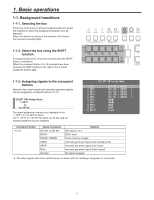
1. Basic operations 1-1-4. Selecting the bus mode The bus mode can be set by the following menu operations. [13] Operation Menu 5. Bus Mode A/B: When the slide lever is at side A, the signals selected by the A bus are replaced PGM materials. When the slide lever is at side B, the signals selected by the B bus are replaced PGM materials. PGM (A)/PST (B): Using a flip-flop system, the signals selected by the A bus are always replaced PGM materials, and the signals selected by the B bus are always replaced PST materials. PGM (B)/PST (A): Using a flip-flop system, the signals selected by the B bus are always replaced PGM materials, and the signals selected by the A bus are always replaced PST materials. 1-1-5. Selecting the transition type Use the MIX button and WIPE button to select the background transition mode. 1-1-6. Manual transitions Operate the slide lever to execute transitions manually. If the slide lever is moved while an auto transition is executed, operation will switch to manual as soon as the position of the slide lever has gone beyond the amount of the transition which has been executed. The bus tally indicators on the left of the lever show the program output statuses. When only indicator A is lighted: Only the A bus is output When both indicators A and B are lighted: Transition underway When only indicator B is lighted: Only the B bus is output [13] Operation Menu 7. Slide Lever Any of the following targets for which the transition is to be executed can be set by operating the slide lever. BKGD: Background transition KEY: Key transition PinP: PinP transition NoAsign: Transitions are not executed even when the slide lever is operated. 6
-
 1
1 -
 2
2 -
 3
3 -
 4
4 -
 5
5 -
 6
6 -
 7
7 -
 8
8 -
 9
9 -
 10
10 -
 11
11 -
 12
12 -
13
-
14
-
15
-
16
-
17
-
18
-
19
-
20
-
21
-
22
-
23
-
24
-
25
-
26
-
27
-
28
-
29
-
30
-
31
-
32
-
33
-
34
-
35
-
36
-
37
-
38
-
39
-
40
-
41
-
42
-
43
-
44
-
45
-
46
-
47
-
48
-
49
-
50
-
51
-
52
-
53
-
54
-
55
-
56
-
57
-
58
-
59
-
60
-
61
-
62
-
63
-
64
-
65
-
66
-
67
-
68
 |
 |
