Panasonic FV-07VFH3 FV-07VFH3 Owner's Manual (English) - Page 10
Installation, Joist Mounting, Continued, Between, Joist Mounting
 |
View all Panasonic FV-07VFH3 manuals
Add to My Manuals
Save this manual to your list of manuals |
Page 10 highlights
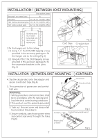
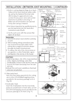
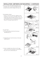
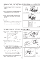
INSTALLATIONⅠ(BETWEEN JOIST MOUNTING-Ⅰ) CONTINUED ④ Fix the louver assembly with the 3 of the M4X8 mechanical screws in the accessory. (Fig.18) ⑤ Install the filter mesh again and attach the unclenched screw caps again.(Fig.19) Screw caps(2 pcs) 10.Paste the switch labels provided in the accessory package on the switch panel. (Fig.20) [Optional] Attach the given switch labels (in accessories) on the wall switch (not included) as shown in the diagram for clearer indication.(Fig.20) On Heat INSTALLATION Ⅱ(JOIST MOUNTING) 3" 3" 1. Make a hole of 10 5 X 10 5 inches (270 X 270mm) adjacent to a joist.(Fig.21) 10 3" 5( 27 0) Adaptor 3" (270) Joist 1 0 5 2. Assemble the hanger unit. Fig.21 Put the adaptor into the hanger holder. (Fig.22) 3. Fix the hanger unit to the ceiling. (1) Using 1 of the ST4.2X30 tapping screws provided in the accessory package to fix the hanger unit to the ceiling.(Fig.23) (2) Using 2 of the ST4.2X30 tapping screws provided in the accessory package to fix the hanger unit to the joist.(Fig.24) 4.Slip the circular duct onto the adaptor and secure it with duct tape.(Fig.24 10 Vent Off Fig.18 Fig.19 Switch labels Fig.20 Hanger holder Fig.22 Fig.23 Circular duct Duct tape Fig.24
-
 1
1 -
2
-
3
-
4
-
 5
5 -
 6
6 -
 7
7 -
 8
8 -
 9
9 -
 10
10 -
 11
11 -
 12
12
 |
 |
