Panasonic FV-07VFH3 FV-07VFH3 Owner's Manual (English) - Page 9
body.Fig.16
 |
View all Panasonic FV-07VFH3 manuals
Add to My Manuals
Save this manual to your list of manuals |
Page 9 highlights
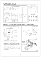
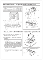
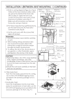
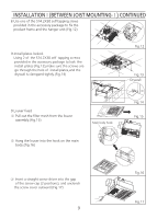
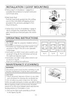
INSTALLATIONⅠ(BETWEEN JOIST MOUNTING-Ⅰ) CONTINUED 8.Use one of the ST4.2X30 self-tapping srews provided in the accessory package to fix the product frame and the hanger unit.(Fig.12) 9.Install plates locked. Using 2 of the ST4.2X30 self-tapping screws provided in the accessory package to lock the install plates (Fig.13),make sure the screws are go through the hole of install plates,and the drywall is clampped tightly.(Fig.14) Fig.12 Fig.13 Drywall 9.Louver fixed ① Pull out the filter mesh from the louver assembly.(Fig.15) Main body hook ② Hang the louver into the hook on the main body.(Fig.16) Fig.14 Fig.15 ③ Insert a straight screw driver into the gap of the screw cap (2 positions), and unclench the screw cover outward.(Fig.17) 9 Fig.16 Fig.17
-
 1
1 -
2
-
3
-
 4
4 -
 5
5 -
 6
6 -
 7
7 -
 8
8 -
 9
9 -
 10
10 -
 11
11 -
 12
12
 |
 |
