Panasonic FV-07VFH3 FV-07VFH3 Owner's Manual (English) - Page 6
Wiring Diagram, Installation, Between Joist Mounting
 |
View all Panasonic FV-07VFH3 manuals
Add to My Manuals
Save this manual to your list of manuals |
Page 6 highlights
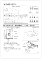
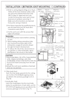
WIRING DIAGRAM INSTALLATIONⅠ(BETWEEN JOIST MOUNTING) Top view of the recommended installation. Wall Unit:inches(mm) Unit:inches(mm) 1 0 (270) 63(1600) 1" 31 (800) 2 3" 5 Air duct Product Bathroom Bathtub 17 3" 4 (450) The bathroom size may affect the room heating result of this product. 3" 3" 1.Make a hole of 10 X 10 inch(270 X 5 5 270mm in the ceiling between joist.(Fig.1) 2.Assemble the hanger unit Insert the suspension brackets into hanger holder and put the adaptor into the hanger holder.(Fig.2) Hanger holder Adaptor 10 3"(270) 5 Fig.1 Suspension brackets Fig.2 6
-
 1
1 -
 2
2 -
 3
3 -
 4
4 -
 5
5 -
 6
6 -
 7
7 -
 8
8 -
 9
9 -
 10
10 -
 11
11 -
 12
12
 |
 |

6
WIRING DIAGRAM
INSTALLATION
Ⅰ
(BETWEEN JOIST MOUNTING)
Top view of the recommended installation.
1.Make a hole of 10
10
inch(270
270mm in the ceiling between j
ist.(Fig.1)
X
X
o
2.Assemble the hanger unit
Insert the suspension
and put the adaptor
(Fig.2)
brackets into hanger
holder
into the hanger
holder.
The bathroom size may affect the
room heating result of this product.
10
(270)
10
(270)
Fig.2
Fig.1
Suspension
brackets
Hanger
holder
Adaptor
Unit:inches(mm)
Wall
Air duct
Product
Bathroom
Bathtub
63(1600)
31
(800)
17
(450)
Unit:inches(mm)
1"
2
3"
4
3"
5
3"
5
3"
5
3"
5