Panasonic FV-07VFH3 FV-07VFH3 Owner's Manual (English) - Page 11
Installation, Joist Mounting, Operating Instructions, Maintenance Cleaning
 |
View all Panasonic FV-07VFH3 manuals
Add to My Manuals
Save this manual to your list of manuals |
Page 11 highlights
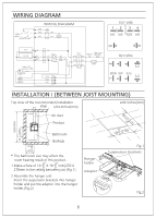
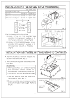
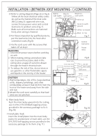
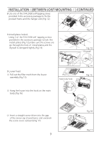
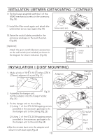
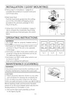
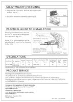
INSTALLATION Ⅱ(JOIST MOUNTING) 5.Follow step 5 of installation Ⅰ(page 8) to complete the connection of power wires and control lead wires. 6.Main body fixed. Push the main body upward into the ceilling, use 4 of the ST4.2X30 self-tapping screws provided in the accessory package to fix it. (Fig.25 & Fig.26 ) 7.Follow step 7,8,9,10 of installationⅠ(page 910) to complete the install plate fixed,install plate locked,louve fixed and paste the switch labels. OPERATING INSTRUCTIONS WARNING The heater shall be properly installed before it is used. 1.Fan heater is in STOP stage when switch is set as shown in Fig.27.The unit is not operated in this stage. 2.Fan heater is in HEAT mode when switch is set as ahown in Fig.28.The unit blown out hot air. The bathroom become warm. 3.Fan heater is in VENT mode when switch is set as shown in Fig.29. Fresh air is caming into bathroom. MAINTENANCE (CLEANING) WARNING: Disconnect power source before working on unit. Routine maintenance must be done every year. Heat On Fig.27 CAUTION: 1.Never use petrol, benzene, thinner or any other such chemicals for cleaning the ventilating fan. 2.Do not allow any water to get into the motor. 3.Do not soak resin parts in water over 60°C(140°F). Before cleaning, make sure the power has been turned off at the circuit breaker panel and that the heating element of the heater is cool. ① Pull out the filter mesh assembly as shown in the figure (Fig.30). 11 Vent Off Heat On Fig.28 Vent Off Heat On Fig.25 Joist Fig.26 Fig.29 Fig.30 Vent Off
-
 1
1 -
2
-
3
-
4
-
5
-
 6
6 -
 7
7 -
 8
8 -
 9
9 -
 10
10 -
 11
11 -
 12
12
 |
 |
