Panasonic FV-10VS1 Installation Instructions
Panasonic FV-10VS1 Manual
 |
View all Panasonic FV-10VS1 manuals
Add to My Manuals
Save this manual to your list of manuals |
Panasonic FV-10VS1 manual content summary:
- Panasonic FV-10VS1 | Installation Instructions - Page 1
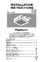
INSTRUCTIONS Ventilating Fan FV-05VS1 FV-08VS1 FV-10VS1 e Panasonid READ AND SAVE THESE INSTRUCTIONS. Please read these instructions carefully before attempting to install, operate or service the Panasonic Ventilating Fan. Failure to comply with instructions Guide to Installation Product Service - Panasonic FV-10VS1 | Installation Instructions - Page 2
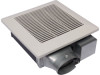
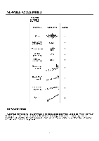
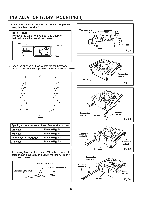
1 Suspension bracket II 1 Suspension 1 bracket III Spacer 1 DESCRIPTION These Panasonic ceiling /wall mount ventilation fans use a sirocco fan driven by a capacitor motor. The motor is designed to have an extended service life with reduced energy consumption. It also incorporates a thermal - Panasonic FV-10VS1 | Installation Instructions - Page 3
(38 Unit: inches (mm) 1 (25) 8 9 3 1/8 78 3 6/8 (95) 7 6 L. 10 1/4 (261) FV-10VS1 (160 6 5/16 1 42) 3 3/4 (94 N N lb a ...... o li 1, - C> 5 13 (330) - Panasonic FV-10VS1 | Installation Instructions - Page 4
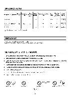
.1" WG. ight lb.( kg) FV-05VS1 3 0.8 18 759 50 9.9 (4.5) FV-08VS1 Exhaust 120 60 3 1.4 26 FV-10VS1 4 1.5 34 Specifications are based not install this ventilating fan where interior room temperature may exceed 104°F (40°C). 2. Make sure that the electric service supply voltage is 120 - Panasonic FV-10VS1 | Installation Instructions - Page 5
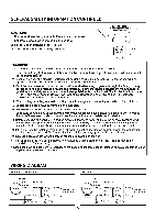
-state control device. 8. Before servicing or cleaning unit, switch power off at service panel and lock the service disconnecting means to prevent power from ' Earth Power supply AC120V 60Hz Earth ground Earth ground FV-10VS1 Fan Body Red Junction box Motor Capacitor White Black White Black - Panasonic FV-10VS1 | Installation Instructions - Page 6
shown below: Adaptor 0 0 0 ° Damper 11 Tape Thumb screw 2. Insert the supension bracket into the fan body and adaptor. (Select the suspension bracket as shown below) A 4 ► Fan body Fan body Fig.1 Suspension bracket I Fig.2-1 'ir Joists Spacing A on center joists Insert Suspension bracket - Panasonic FV-10VS1 | Installation Instructions - Page 7
carefully so that lead wires are not pinched. 7.FV-05VS1 /FV-08VS1: install a circular duct and secure it with duct tape. FV-10VS1: squeeze the circular duct to fit the adaptor, then slipped onto the adaptor and secure it with duct tape. Squeeze 7 Fan body 2 Long screws (ST4.2X20) Fig. 3-2 Joist - Panasonic FV-10VS1 | Installation Instructions - Page 8
(mm) Slot Fig. 6 Mounting spring Ceiling Grille INSTALLATION II (JOIST MOUNTING-II) 1. Disconnect plug connector from receptacle and remove adaptor from fan body before starting installation. Adaptor 2. Insert the suspension bracket into the adaptor and secure it to joists by using long screws - Panasonic FV-10VS1 | Installation Instructions - Page 9
suspension bracket to joists by using long screws (ST4.2X20) and secure it to fan body by using screw II (ST4.2X10) in vertical direction. (Fig. 11 . (Fig. 10) I I Circular duct Joist Conduit Junction box cover Fan body Adaptor claws Fig. 9 Ceiling Thumb screw Plug connector I Receptacle I - Panasonic FV-10VS1 | Installation Instructions - Page 10
adaptor by using thumb screw. (Fig.1 of page 6) 2. Insert the suspension bracket into the bracket cover of adaptor side and the back of the fan body. (Fig.15) (select the suspension bracket according to spacing A as shown below) A 16 inches and 19.2 inches horizontal joist and 19.2 inches vertical - Panasonic FV-10VS1 | Installation Instructions - Page 11
is level and square Joists (perpendicular) with the joists. (Fig. 16) CAUTION: Ensure that distance B is no more than 1/2 inch (13 mm). Adaptor Fan body Junction box 4. Secure the suspension bracket to joists by using long screws (ST4.2X20). (Fig. 17, Fig. 18) Suspension bracket 13 1/4-151 - Panasonic FV-10VS1 | Installation Instructions - Page 12
adaptor by using thumb screw. (Fig. 1 of page 6) Joist 2. Install header between joists by using nails or screws. 3. Install the ventilating fan and secure it by using long screws (ST4.2X20). (Fig. 19, Fig. 20) 4. Follow step 5 to 9 of installation I (page 7, page 8) to complete the installation - Panasonic FV-10VS1 | Installation Instructions - Page 13
, the adaptor shall be faced upward. (Fig. 21) UPI 0 Prohibition 0 Prohibition 1. Disconnect plug connector from receptacle and remove adaptor from fan body before starting installation. (Fig. 22) 0 Prohibition Fig. 21 2. Insert the suspension bracket into the adaptor. (refer to step 2 of - Panasonic FV-10VS1 | Installation Instructions - Page 14
distance C 3/16 inch (5mm). 4. Secure the suspension bracket to studs by using long screws (ST4.2X20). (Fig. 26, Fig. 27) 5. Secure the suspension bracket to fan body by using / screw If (ST4.2X10) (refere to Fig. 4 of page 7). 6. Complete the duct work and wiring (refere to step 5 to 7 of the - Panasonic FV-10VS1 | Installation Instructions - Page 15
must be done every year. Slot Mounting spring CAUTION: 1. Never use petrol, benzene, thinner or any other such chemicals for cleaning the ventilating fan. 2. Do not allow water to enter motor. 3. Do not immerse resin parts in water over 60°C. Glove l Grille 1. Remove grille. (Squeeze mounting - Panasonic FV-10VS1 | Installation Instructions - Page 16
fill or batt insulation can be placed directly over the fan housing in the attic. Panasonic fans and fan/light combination units do not create excessive heat that is a common problem with recessed light fixtures or some competitors' fan/light combinations. Our efficient, cool-running motors and our
-
 1
1 -
 2
2 -
 3
3 -
 4
4 -
 5
5 -
 6
6 -
 7
7 -
8
-
9
-
10
-
11
-
12
-
13
-
14
-
15
-
16
 |
 |
INSTALLATION
INSTRUCTIONS
Ventilating
Fan
e
Panasonid
FV-05VS1
FV-08VS1
FV-10VS1
READ
AND
SAVE
THESE
INSTRUCTIONS.
Please
read
these
instructions
carefully
before
attempting
to
install,
operate
or
service
the
Panasonic
Ventilating
Fan.
Failure
to
comply
with
instructions
could
result
in
personal
injury
and/or
property
damage.
Please
retain
this
booklet
for
future
reference.
Table
of
Contents
Supplied
Accessories
2
Description
2
Dimensions
3
Specifications
4
Unpacking
4
General
Safety
Information
4-5
Wiring
Diagram
5
Installation
I
(
Joist
Mounting
-I
)
6-8
Installation
II
(
Joist
Mounting
-II
)
8-9
Installation
III
(
I
-Joist
Mounting
)
10
Installation
IV(
Between
Joist
Mounting
)
10-11
Installation
V
(
Wooden
Header
)
12
Installation
VI(
In
Existing
Construction
)
12
Installation
VII
(
Wall
Installation
-I
)
13
Installation
VIII
(
Wall
Installation
-II
)
14
Installation
IX
(
Wall
Installation
-III
)
14-15
Maintenance
15-16
Practical
Guide
to
Installation
16
Product
Service
16