Panasonic FV-10VS1 Installation Instructions - Page 11
Installation, Between, Joist, Mounting, Continued
 |
View all Panasonic FV-10VS1 manuals
Add to My Manuals
Save this manual to your list of manuals |
Page 11 highlights
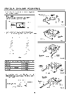
INSTALLATION IV ( BETWEEN JOIST MOUNTING ) CONTINUED 3. Insert the fan body between joists. Make sure the fan body is level and square Joists (perpendicular) with the joists. (Fig. 16) CAUTION: Ensure that distance B is no more than 1/2 inch (13 mm). Adaptor Fan body Junction box 4. Secure the suspension bracket to joists by using long screws (ST4.2X20). (Fig. 17, Fig. 18) Suspension bracket 13 1/4-151/2 (336-394) 18 112-18 3/4 (419-480) 21 1/4-23 1/2 ( 540-597 ) D III B no more than 1/2 (13) Unit: inches (mm) Fig. 16 2 Long screws (ST4.2X20) 5. Secure the suspension bracket to fan body by using screw II (ST4.2X10). (Fig. 18) 6. Follow step 5 to 9 of installation I (page 7, page 8) to complete the installation work. 11 lat0groisMal law 0.,71741=1~t,' w Joist Fig. 17 4 Long screws 2 Screw /I (ST4.2X20) (ST4.2X10) Joist Fig. 18
-
 1
1 -
2
-
3
-
4
-
5
-
 6
6 -
 7
7 -
 8
8 -
 9
9 -
 10
10 -
 11
11 -
 12
12 -
 13
13 -
 14
14 -
 15
15 -
 16
16
 |
 |
