Panasonic WJ-PR204 Operating Instructions - Page 21
Parts and functions, 2.1 WJ-PR204/WJ-PR204E/WJ-PR201/WJ-PR201E (connects to the network device)
 |
View all Panasonic WJ-PR204 manuals
Add to My Manuals
Save this manual to your list of manuals |
Page 21 highlights
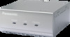
2 Parts and functions 2 Parts and functions 2.1 WJ-PR204/WJ-PR204E/WJ-PR201/WJ-PR201E (connects to the network device) Front view A POWER Indicator Displays the status of receiver side unit (see page 24). B LAN Indicator Indicates that the receiver side unit is connected to the network equipment (see page 24). ABC C COAXIAL Indicator Indicates that the receiver side unit is connected to the camera side unit (see page 24). Note The WJ-PR204 is used as an example in some of the illustrations in this document. Rear view WJ-PR201, WJ-PR201E A C A BNC connector Connects the receiver side unit to the camera side unit with a coaxial cable (see page 37). B Network connector B Connects the receiver side unit to a network device with an Ethernet cable (see page 38). C DC IN Connects the receiver side unit to the power outlet with the included AC cord (see page 39). Operating Instructions 21
-
 1
1 -
2
-
3
-
4
-
5
-
6
-
7
-
8
-
9
-
10
-
11
-
12
-
13
-
14
-
15
-
 16
16 -
 17
17 -
 18
18 -
 19
19 -
 20
20 -
 21
21 -
 22
22 -
 23
23 -
 24
24 -
 25
25 -
 26
26 -
27
-
28
-
29
-
30
-
31
-
32
-
33
-
34
-
35
-
36
-
37
-
38
-
39
-
40
-
41
-
42
-
43
-
44
-
45
-
46
-
47
-
48
-
49
-
50
-
51
-
52
-
53
-
54
-
55
-
56
-
57
-
58
-
59
-
60
 |
 |
