Panasonic WJ-PR204 Operating Instructions - Page 39
LINK indicator Green, AC adapter, output connector, Cable fixing, hooks, AC cord accessory
 |
View all Panasonic WJ-PR204 manuals
Add to My Manuals
Save this manual to your list of manuals |
Page 39 highlights
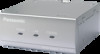
4 Connecting the Unit 7. Connect the output connector of the AC adapter (accessory) to the DC jack at the rear of the receiver side unit, and plug the AC power cord into the power outlet. AC adapter output connector Cable fixing hooks AC cord (accessory) • Secure the cables from the AC adapter output connector using the cable fixing hooks at the rear of the receiver side unit. • Do not place the AC adaptor on top of the receiver side unit. • When you operate the receiver side unit, the power outlet should be near the receiver side unit and easily accessible. To prevent the AC cord from being disconnected if it is pulled, do not place objects near the power outlet. 8. Turn the power on for the network cameras and network devices, then check the indicators of the camera side unit and the receiver side units. LINK indicator (Green) POWER indicator (Green) LAN indicator (Green) COAXIAL indicator (Green) • If the indicator does not light correctly, see "Troubleshooting" on page 51. Operating Instructions 39
-
 1
1 -
2
-
3
-
4
-
5
-
6
-
7
-
8
-
9
-
10
-
11
-
12
-
13
-
14
-
15
-
16
-
17
-
18
-
19
-
20
-
21
-
22
-
23
-
24
-
25
-
26
-
27
-
28
-
29
-
30
-
31
-
32
-
33
-
 34
34 -
 35
35 -
 36
36 -
 37
37 -
 38
38 -
 39
39 -
 40
40 -
 41
41 -
 42
42 -
 43
43 -
 44
44 -
45
-
46
-
47
-
48
-
49
-
50
-
51
-
52
-
53
-
54
-
55
-
56
-
57
-
58
-
59
-
60
 |
 |
